diy solar

diy solar

Solar Consultant says no fuse/breaker required between Pylontech batteries & bus bar -- pass the smell test?

AlaskanNoob

Solar Enthusiast
Joined
Feb 20, 2021
Messages
906
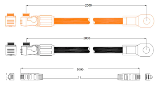
We've seen it done both ways, the Pylontech manual says protection is required between the batteries and the inverter which, I suppose, this design does but many people seem to think fusing or breakers should be put on the Pylontech battery cables before the bus bar and as close to the batteries as possible (any closer than about 6.5 feet would require us to cut the supplied Pylontech cables to make that happen since the supplied Pylontech cables are 6.5 feet long). The consultant we hired thinks we should do it like this instead without that protection. He says:

As discussed the battery cables connecting to the bus bar have the concerning source of power at the batteries. Thus, unless you can mount the 125A class T fuse you mention right at each battery, there is no point in protecting this wire run. If the class T fuse is at the bus bar, it only protects the bus bar, which does not need protection. The best place for the class T fuses in this installation is as shown - protecting the cables that connect equipment from the high current possible from the batteries. Keeping the battery lead cables short is the most important concern that you have already addressed.

Is he right, or should we put 125A fusing or breakers (since the Pylontech cables are rated to 125A max) between the Pylontech battery cables and the bus bar in addition to the t-fuses he has shown?

This is his design of our system.
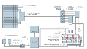
Updated One Line Schematic.png
 
Last edited:
any closer than about 6.5 feet would require us to cut the supplied Pylontech cables to make that happen since the supplied Pylontech cables are 6.5 feet long)
The consultant is technically correct but in practice- quite wrong.
Fuse at the batteries!
Just use your 2-meter cables as is and place them neatly out of the way (provided they are sized appropriately
 
Last edited:
Fues between the Battery and the BusBar (where you have the ovals), even if it has to be done at the Busbar. It won't be able to protect the wire between the battery and the fuse, but it will protect from anything after the fuse. Without the fuses, if any of the batteries have a problem, they will all have a problem.
 
We've seen it done both ways, the Pylontech manual says protection is required between the batteries and the inverter which, I suppose, this design does but many people seem to think fusing or breakers should be put on the Pylontech battery cables before the bus bar and as close to the batteries as possible (any closer than about 6.5 feet would require us to cut the supplied Pylontech cables to make that happen since the supplied Pylontech cables are 6.5 feet long). The consultant we hired thinks we should do it like this instead without that protection. He says:


Is he right, or should we put 125A fusing or breakers (since the Pylontech cables are rated to 125A max) between the Pylontech battery cables and the bus bar in addition to the t-fuses he has shown?

This is his design of our system.
View attachment 140047
Do your batteries each have their own on/off breaker attached to the battery?
 
I guess I could see it if the distance between the battery bus bar is super short and the battery BMS would shut off the circuit at a lower current than the wire can handle. Also, If there is no way a positive lead is not at all close to a ground connection.
 
The consultant is technically correct but in practice- quite wrong.
Fuse at the batteries!
Just use your 2-meter cables as is and place them neatly out of the way (provided they are sized appropriately

I understand I need to use a t-fuse. I've seen the t-fuse block. The 6.5' cables that come with the battery use a snap type head to plug onto the battery terminals. I assume I should cut this cable close to the terminal, say 1 foot, and install terminals on the cut ends, then connect it to a fuse block? I would have to mount the fuse block for each set of cables on the battery rack itself.

Or are you envisioning something else?cables.png
 
I've been pondering the best practice for this situation. It seems most people think of the battery as the source of the current in the event of a fault. However, there are three other batteries pushing current into the bus bar, so it actually has a higher available fault current than any individual battery. For instance, if your batteries were actually fused at their rated 125 amp limit, the bus bar could supply 375 amps from three batteries back into a failed BMS in the fourth battery without blowing any of their fuses.

I guess a similar situation is the fusing of parallel solar panel strings. You don't fuse a string a panels because it might suddenly over produce current. You fuse a string of panels to prevent the parallel strings from pushing excessive current through a failed string, which could catch it on fire.

Its not so simple with batteries though because an individual battery can produce excessive current for long enough to start a fire. Its all a matter of where you imagine the problem occurring.
 
You could just add a breaker as well. Either works aok, but I agree there should be one or the other after the batteries and before the busbar.
A breaker rated for 20k amps?
However, there are three other batteries pushing current into the bus bar, so it actually has a higher available fault current than any individual battery. For instance, if your batteries were actually fused at their rated 125 amp limit, the bus bar could supply 375 amps from three batteries back into a failed BMS in the fourth battery without blowing any of their fuses
375A would blow a 125A fuse before that happens- and everything after the busbar would be fuses or breakers of the appropriate rating….
 
That connector at the battery is a specialty type, so I understand your reservations.

It looks like those are nominal 96 volts per battery, so your setup would be ~ 190 volts for each string?

If it were me, I would prefer to have a way to at least disconnect the (+) wire of each battery string from the bus bar "somehow", ideally with a breaker. Otherwise, start up and maintenance is going to be a real pain.

I am assuming that you are using a very good bus bar / isolation method for that DC voltage.

As drawn, I don't seen an obvious way to de - energize the bus bar, and even if the batteries are disconnected, that would take a lot of PV breakers being switched off to cut the solar side. Maybe it is ok - not sure.

I am no expert, but I don't think in CA we could install that since it does not have any obvious way to shut it all down with a fireman's switch.

Perhaps the pre-charge circuit side is just not shown for simplicity.

Just kicking around ideas - not criticizing.
 
Iono. That's a lot of amps.
That is why people use Class T fuses- they are rated for the short-circuit potential that a LiFePo battery could dump out.
If you use an ordinary fuse or circuit breaker it won’t have the disconnect capacity to protect anything in a Bad Event.

A properly rated fuse or circuit breaker will never blow, most likely. But if a Bad Event occurs, it WILL disconnect instead of potentially arcing itself shut or sustaining an arc that will burn down the house.
 
If each battery is wired individually to the bus bar, I think the fuse would need to be rated for 10K short circuit amps. I imagine that would still drive a t-fuse to be safe, or a massively expensive breaker if one exists.
 
If each battery is wired individually to the bus bar, I think the fuse would need to be rated for 10K short circuit amps. I imagine that would still drive a t-fuse to be safe, or a massively expensive breaker if one exists.
Right. And it doesn’t matter the cumulative amps: each circuit after the busbar will be fused appropriately.

I think people forget amps only show up in a short or with a load.
 
Right. And it doesn’t matter the cumulative amps: each circuit after the busbar will be fused appropriately.

I think people forget amps only show up in a short or with a load.

Would one of the midnight solar breakers work? They have pretty high interrupt current ratings.
 
I don’t know the products from Midnite. I’d look them up- they are one of the suppliers that people depend on for safe ratings and functionality. Their website should have specs for their DC breakers.
 
Back
Top