• Have you tried out dark mode?! Scroll to the bottom of any page to find a sun or moon icon to turn dark mode on or off!

diy solar

diy solar

Solar diversion load into hot water heater

Aakelley

New Member
Joined
Feb 3, 2022
Messages
140
I am a few weeks away from adding another 1kw in panels to my mobile system, which will give me 2.6kw total. I will wait to see what the system production looks like once everything is in place, but there have already been a few days where I am generating more energy than my batteries (10kwh of LifePO4) can absorb. Of course there are many days where that is not the case, hence the additional panels ;-).

In anticipation of wanting a diversion load, I have been playing around with converting my small hot water heater to run on DC and front ending the circuit with a voltage sensitive relay that would kick on when batteries are nearing 100% SoC voltage and send power through a high amp relay to a DC heating element (swap out the AC one that's in there presently). Sharing out to see if there is anything I might be missing or any better part suggestions?
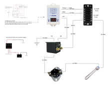
Skoolie Solar System Design - Hot Water Heater.png
Parts I plan to use:
 
My concern would be that voltage change is quite small compared to SoC, so not a good indicator. Coupled with the issue that voltage across your battery will be highly dependent on load drawn.

So, I could imagine that the system could easily get into an oscillation. i.e. the batteries get near full and trigger your "on" voltage, the relay switches the heater on which is a high load. That in turn will drop battery voltage below your "off" voltage. The heater will turn off and the batteries now have no load. So the cells will quickly recover their voltage and turn the relay on again.

It would be much better if you can interface a micro-controller or similar to get the true SoC from your inverter/charge controller and use the SoC value to switch the load on. Or use a smart-shunt to get the SoC if you can't get it elsewhere.
 
snap thermostat in line with element and carrying DC is likely to fail.
I would use it (and the over temperature switch) to control relay coil.
Put a snubber on the coil.

Relay will be a single point of failure. Make sure temperature/pressure relief valve works.

There is a PV MPPT product for heating elements. It is simpler because it doesn't need an inductor, just capacitors and PWM to heater (zero volt times should allow thermostats to work, so long as transistors don't fail shorted.)
 
My concern would be that voltage change is quite small compared to SoC, so not a good indicator. Coupled with the issue that voltage across your battery will be highly dependent on load drawn.

So, I could imagine that the system could easily get into an oscillation. i.e. the batteries get near full and trigger your "on" voltage, the relay switches the heater on which is a high load. That in turn will drop battery voltage below your "off" voltage. The heater will turn off and the batteries now have no load. So the cells will quickly recover their voltage and turn the relay on again.

It would be much better if you can interface a micro-controller or similar to get the true SoC from your inverter/charge controller and use the SoC value to switch the load on. Or use a smart-shunt to get the SoC if you can't get it elsewhere.
Solid point on the potential for an oscillation. I know the voltage relay has a timer function. Wondering if I can use that to delay the opening of the circuit until a voltage drop would have recovered? Will dive into the doc on it and see what's possible there.

I have the inverter connected to an Orange Pi running solar assistant. That has an MQTT integration so will look into that as an option.
 
snap thermostat in line with element and carrying DC is likely to fail.
I would use it (and the over temperature switch) to control relay coil.
Put a snubber on the coil.

Relay will be a single point of failure. Make sure temperature/pressure relief valve works.

There is a PV MPPT product for heating elements. It is simpler because it doesn't need an inductor, just capacitors and PWM to heater (zero volt times should allow thermostats to work, so long as transistors don't fail shorted.)
Solid call on where to put the thermostat. Redoing the diagram to reflect.

What's a snubber?

Any links to the PV MPPT Product? Would it be something I would switch to manually or leave in the circuit path and it would figure out when to activate?
 

This may have been it:


At first, you would think MPPT couldn't be done without inductors. But those are only needed for constant voltage output, like battery charger. PWM of resistive load regulates power draw, and capacitor on PV output converts that to average current draw, which in turn holds PV array at a voltage.

Switching it to an array used for battery/inverter at other times would mean PV wire transfer switch. It is also best not to switch HV DC with current flowing; some manufacturers of GT PV inverters (SMA) recommend turning off AC first.

If you have inverter AC, heater can be a dump load. But that will be just on/off, or a couple steps of power level. We would prefer continuously variable and always presenting a "real" (resistive) load, PF = 1.0

The PV direct heater MPPT would maximize power delivered, except when thermostat opens.
 
Ah thanks for the tip - will look to see what the concerns were. Any other better DC thermostats you know of?

Not sure, but we've seen 48VDC water heater elements with built-in thermostat. The thermostat itself was stamped with AC rating, and failed with the higher voltage of a nominal 48V system.

Thermostats (usually?) have small contact travel from bimetallic deflection. AC can be interrupted with small gap, but DC can't.
The thermostats and switches often have low current ratings for modest DC voltage, so "pilot duty" is fine. But I figure inductive loads will burn them, ergo the snubber.

You can get DC breakers including polarized which have magnet to deflect arc. Some breakers are remove trip. Ways to set up protection circuits, but I would like fail-safe or dead-man devices which don't require continuity and current flow to trip. Could hold on with electricity, but then needs continuous power supply to not trip, less practical for PV direct.
 
I know the voltage relay has a timer function. Wondering if I can use that to delay the opening of the circuit until a voltage drop would have recovered?
? the moment I hit 'post reply' I thought... well, he could add a timer to make sure the minimum on and off time was (say) 1 or 5 minutes to avoid the issue I dreamed up!

I have the inverter connected to an Orange Pi running solar assistant. That has an MQTT integration so will look into that as an option.
Sounds good. I am nearing completion of an AC immersion heater diverter project that gets the 'spare' energy data from our monitoring system over MQTT ?‍?- the plan seems to be working well so far.

As for the discussion above about relays / bi-metallic strips / arcing and the like.... what DC current and voltage are you thinking of switching?

Personally I'd aim for solid-state if possible... so in my mind, as you've got the Pi and SA and MQTT, you could deploy a digital temp sensor (DS18B20 or similar) connected to ESP32 that is getting SoC info via MQTT and switching the heater with a MOSFET or two. i.e. almost same as what I'm doing (though I'm doing PWM using a triac on 240V ac). ??♨️? Just a thought.
 
? the moment I hit 'post reply' I thought... well, he could add a timer to make sure the minimum on and off time was (say) 1 or 5 minutes to avoid the issue I dreamed up!


Sounds good. I am nearing completion of an AC immersion heater diverter project that gets the 'spare' energy data from our monitoring system over MQTT ?‍?- the plan seems to be working well so far.

As for the discussion above about relays / bi-metallic strips / arcing and the like.... what DC current and voltage are you thinking of switching?

Personally I'd aim for solid-state if possible... so in my mind, as you've got the Pi and SA and MQTT, you could deploy a digital temp sensor (DS18B20 or similar) connected to ESP32 that is getting SoC info via MQTT and switching the heater with a MOSFET or two. i.e. almost same as what I'm doing (though I'm doing PWM using a triac on 240V ac). ??♨️? Just a thought.
My plan is to feed the heating element with 24v so a 600w element would need 25A. I’ve dabbled with arduino but mqtt is all new to me so going to dive into that end of the pool. This is half the reason I love these projects! (Other half is free energy from the sun ?)
 
... so going to dive into that end of the pool. This is half the reason I love these projects! (Other half is free energy from the sun ?)
Pool heated from solar, I trust :cool:

Sounds good - pretty sure 24V / 25A is doable with MOSFETS with a heatsink or two... maybe you could attach the MOSFET heatsink to the water tank, so as not to waste any good energy too :LOL:
 
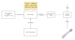
OK, here is v2 based on feedback so far. Big switch is to something more solid state. Not quite comfortable with getting down to the component level (i.e. mofsets), so paying a little more for smart components (Shelly smart relay) to get this up and running. This seem reasonable or missing something again? If in the right direction, any tips on what to use as MQTT broker (default will just be another Orange Pi...solar-assitant.io seems pretty particular on being the only thing running on the one I have)? Any favorite (or ones to avoid) MQTT temperature sensors?
Skoolie Solar System Design - Hot Water Heater v2-2.png
 
Mosquitto seems to be the most common broker in use, from what I have seen. But I am no expert in setting one up, as our monitoring system already had Mosquitto running on a RPi.
 
Sorry - was wondering about hardware specifically. Probably run Home Assistant with Mosquitto added on.
 
Battery SOC would be the best way to trigger this. 100% SOC water heater relay = on, 98% SOC relay = off.

Looks like you could write a python script to get SOC from solar-assistant, and probably use that to trigger a relay driver from the GPIO pins
 
OK so I saw this while posting a similar thread- HOW did this work out? No chance of all mechanical plus (appropriate) charge controller , w/o app?
 
You can buy a voltage relay which turns on at a set voltage and off at another. You still need a relay to switch high currents, preferably solid state. This is a crude method of heating water. Adding Pyhon is like putting falsies on granny. Don't skip on a solid state relay. Never use at more than a third of its current rating. Or you might have this.
 
It did have heat sink compound. Aluminum sheet metal may not have been as good a heatsink as thicker base + fins.
He observed little temperature rise in normal use, thinks may have been greater heating entire tank from cold on a hot day.

Triac may not have burned up, he noted. If at edge of power consumption spec, need to evaluate cooling. Maybe better attached to cold water pipe? Should have used higher amperage SSR.

I don't believe copper PCB trace would cause the burned package, would just pop. Sometimes used as a fuse. Solder blob on trace maybe would act as heating element.

"Arcing", he said? Only the thermostat electromechanical contacts. Not the triac (which turns off at zero crossings, anyway.)

Easier way to go, which I have done, is use that harbor freight timer to switch 120V directly to 240V element. I have worn out the timers on larger loads (espresso machine), but 3600W heating element at half voltage would draw 900W. "Resistive", not "tungsten" load. Heavier electromechanical relay would be a way to go.
 
That was a TO-220 package and it was on galvanized steel for a heat sink. That circuit board probably couldn't handle more than 10A and the solder melted. I bought a machine and spare parts dirt cheap at auction. It had hundreds of Crydom D4875 solid state relays. I sold a couple hundred of these used ones for $11 each to a guy who shipped them to South America. He was thrilled to get them at that price. I made a bundle. You won't see one of those fail. Even on AliExpress one listing said to derate 30% for pure resistance. Tungsten was derated 70%. Got to thank them for being that honest. You need a massive heatsink on these to get reliability. I saw one other post where Crydom relay was $143. You get what you pay for.
 

diy solar

diy solar
Back
Top