Is my system correct. Will be 12v and wired parallel, includes 2-240w panels, 40a mppt solar charge controller, 1500 pure sine wave inverter, 2-105ah agm batteries, 250a breaker, gland, y branch connectors, mc4 extension cords, on/off switch. 40amp fuse for charge controller, 20a inline fuse for solar, 150a breaker for battery, 4 awg wires to connect batteries in parallel and wires for battery to inverter, 8 awg wires for controller to battery


You are using an out of date browser. It may not display this or other websites correctly.
You should upgrade or use an alternative browser.
You should upgrade or use an alternative browser.
Solar help for bus life
- Thread starter Kike12
- Start date
MichaelK
Solar Wizard
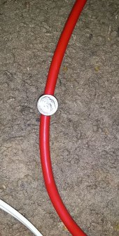
I think 4 gauge wire is inadequate to connect your batteries to a 1500W inverter. At full power, your inverter will be pulling 1500W/12V = 125A from your batteries. Here's a chart that indicates maximal safe amperage for a certain gauge of wire. Your 4 gauge connection is only somewhat better than 50% of what is needed.
You might get away with 4 gauge only if you never run anything that consumes more than about 800-850W. But, it's in your own best interest to do things properly from the start.
I assume you'll mount your panels laying flat. Flat, most likely their maximal output will be 60% of their rated amperage, so expect to see (480W/13Vcharging) X 60% = 22.2A, so 8 gauge will be adequate to connect your controller.
Whinny
Solar Enthusiast
- Joined
- Dec 24, 2020
- Messages
- 399
That seems to be a very conservative ampacity table. Anybody know why the discrepancy?
So I will need 2 Guage instead of 4I think 4 gauge wire is inadequate to connect your batteries to a 1500W inverter. At full power, your inverter will be pulling 1500W/12V = 125A from your batteries. Here's a chart that indicates maximal safe amperage for a certain gauge of wire. Your 4 gauge connection is only somewhat better than 50% of what is needed.
You might get away with 4 gauge only if you never run anything that consumes more than about 800-850W. But, it's in your own best interest to do things properly from the start.
I assume you'll mount your panels laying flat. Flat, most likely their maximal output will be 60% of their rated amperage, so expect to see (480W/13Vcharging) X 60% = 22.2A, so 8 gauge will be adequate to connect your controller.
View attachment 81627
Whinny
Solar Enthusiast
- Joined
- Dec 24, 2020
- Messages
- 399
You should check your manual for wire and fuse size. I your product is unsupported you can "borrow" a manual from another brand for guidance.
See page 16.....
See page 16.....
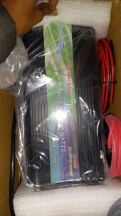
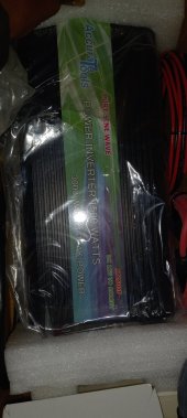
What brand inverter? If you are going to use those wires you need to fuse appropriately.
You should also post photos or links to your solar controller and panel specs.
Attachments

What brand inverter? If you are going to use those wires you need to fuse appropriately.
You should also post photos or links to your solar controller and panel specs.
Attachments
1500W / 12V / 0.85 = 150A. For 150A you need at least 1AWG marine grade high quality pure copper stranded wire rated for 105ºC between the batteries and the inverter. And you need a 200A fuse at the battery. 1/0AWG might be better.Is my system correct. Will be 12v and wired parallel, includes 2-240w panels, 40a mppt solar charge controller, 1500 pure sine wave inverter, 2-105ah agm batteries, 250a breaker, gland, y branch connectors, mc4 extension cords, on/off switch. 40amp fuse for charge controller, 20a inline fuse for solar, 150a breaker for battery, 4 awg wires to connect batteries in parallel and wires for battery to inverter, 8 awg wires for controller to battery
For a 40A charge controller you need a 50A fuse. If you use a 40A then you risk nuisance trips. 8AWG for the controller will be the minimum size but the wires must be short - 10' roundtrip at the most. 6AWG would be better.
You mention a 250A breaker in your list but you don't say what it is for.
What you sent me says 200a fuse and #2 Guage wireYou should check your manual for wire and fuse size. I your product is unsupported you can "borrow" a manual from another brand for guidance.
See page 16.....
I purchased the 250a breaker for between battery and inverter.1500W / 12V / 0.85 = 150A. For 150A you need at least 1AWG marine grade high quality pure copper stranded wire rated for 105ºC between the batteries and the inverter. And you need a 200A fuse at the battery. 1/0AWG might be better.
For a 40A charge controller you need a 50A fuse. If you use a 40A then you risk nuisance trips. 8AWG for the controller will be the minimum size but the wires must be short - 10' roundtrip at the most. 6AWG would be better.
You mention a 250A breaker in your list but you don't say what it is for.
The charge controller will be about 6-7 inches away
Last edited:
But you were planning to use 4AWG wire. 250A is way more than you can use with 4AWG. A fuse's job is to protect a wire. But it can't do that if the fuse's rating is higher than what the wire can handle.I purchased the 250a breaker for between battery and inverter.
You only need a 200A fuse for the inverter but that assumes you use 1AWG or 1/0AWG as I mentioned in my previous post.
Everyone is telling me different stuff I was told 4awg and 150a breaker. I'm making sure I have the right information so I can purchase the wire and fusesBut you were planning to use 4AWG wire. 250A is way more than you can use with 4AWG. A fuse's job is to protect a wire. But it can't do that if the fuse's rating is higher than what the wire can handle.
You only need a 200A fuse for the inverter but that assumes you use 1AWG or 1/0AWG as I mentioned in my previous post.
So I need 1awg and 150A for batteries to parallel and batteries to inverter and 8awg is good for controller the distance should be between 6-7 or less
When working out the battery wiring you need to determine the largest load that you will have to deal with. That is typically the inverter. If you have lots of DC loads too then that would add to it.Everyone is telling me different stuff I was told 4awg and 150a breaker. I'm making sure I have the right information so I can purchase the wire and fuses
So I need 1awg and 150A for batteries to parallel and batteries to inverter and 8awg is good for controller the distance should be between 6-7 or less
The common calculation is inverter watts / lowest battery voltage / inverter efficiency. That results gives you the max amps that will be pulled from the battery when maxing out the inverter. It's safest to wire for the largest possible load.
In your case you have 1500W inverter and a 12V battery. It's typical to assume 85% efficiency for the calculation to be safe. So 1500W / 12V / 0.85 = 150A.
So you need wire that can safely handle 150A. There is the chart in post #2. I prefer the chart from Blue Sea Systems since it takes into account amperage and voltage loss. But it assume marine grade copper wire rated to 105ºC. The chart in post #2 is only ampacity but it covers other temperature grades of wire. As you can see from the chart, 4AWG is way too small to handle 150A. 1AWG or 1/0AWG is the correct wire size.
As for choosing the fuse you need two values. 1) The max load, 2) The max safe size fuse for the chosen wire size. You want a fuse between those two values. Too small and it blows when it shouldn't. Too large and it doesn't protect anything. A common guideline is 125% the max load as long as that value is safe for the wire. 125% of 150A is 187.5A. You won't find such a size. Round up to 200A which is still safe for either 1AWG or 1/0AWG.
For things like the SCC you know that its max output is 40A (in this case) so you use a good wire chart and see what size is best for 40A at your needed length. From that you know that 8AWG will work. Use the same guideline as above for the fuse size. 125% of 40A is 50A. 50A is plenty safe for good 8AWG wire.
With this basic knowledge you can work out the proper sizes and question the values others might tell you.
When in doubt, use larger wire. Undersized wire can be dangerous, especially if there is no fuse or the fuse is too big for the wire.
Thank you very much for your help, I really appreciate it. Now I can make my purchase.When working out the battery wiring you need to determine the largest load that you will have to deal with. That is typically the inverter. If you have lots of DC loads too then that would add to it.
The common calculation is inverter watts / lowest battery voltage / inverter efficiency. That results gives you the max amps that will be pulled from the battery when maxing out the inverter. It's safest to wire for the largest possible load.
In your case you have 1500W inverter and a 12V battery. It's typical to assume 85% efficiency for the calculation to be safe. So 1500W / 12V / 0.85 = 150A.
So you need wire that can safely handle 150A. There is the chart in post #2. I prefer the chart from Blue Sea Systems since it takes into account amperage and voltage loss. But it assume marine grade copper wire rated to 105ºC. The chart in post #2 is only ampacity but it covers other temperature grades of wire. As you can see from the chart, 4AWG is way too small to handle 150A. 1AWG or 1/0AWG is the correct wire size.
As for choosing the fuse you need two values. 1) The max load, 2) The max safe size fuse for the chosen wire size. You want a fuse between those two values. Too small and it blows when it shouldn't. Too large and it doesn't protect anything. A common guideline is 125% the max load as long as that value is safe for the wire. 125% of 150A is 187.5A. You won't find such a size. Round up to 200A which is still safe for either 1AWG or 1/0AWG.
For things like the SCC you know that its max output is 40A (in this case) so you use a good wire chart and see what size is best for 40A at your needed length. From that you know that 8AWG will work. Use the same guideline as above for the fuse size. 125% of 40A is 50A. 50A is plenty safe for good 8AWG wire.
With this basic knowledge you can work out the proper sizes and question the values others might tell you.
When in doubt, use larger wire. Undersized wire can be dangerous, especially if there is no fuse or the fuse is too big for the wire.
One more question do I need to add the battery isolator switch to my system
The battery isolater is to prevent your power usage from draining your starting battery. I had one in my van when I had a lead/acid house battery. It worked great, it charged both the starter and the house battery when either solar or alternator voltage was available, when no charging power was available it disconnected the starter battery so I never had to worry about running it down. I used the Blue Seas unit, easy to install and worked great. You don't "need" it, but it is good to have.
I also have 2 generators and shore power. Don't want anything interfering with my alternator since it'll be expensive to change.The battery isolater is to prevent your power usage from draining your starting battery. I had one in my van when I had a lead/acid house battery. It worked great, it charged both the starter and the house battery when either solar or alternator voltage was available, when no charging power was available it disconnected the starter battery so I never had to worry about running it down. I used the Blue Seas unit, easy to install and worked great. You don't "need" it, but it is good to have.
If I did decide to use the isolator how would I connect it to my solar batteriesThe battery isolater is to prevent your power usage from draining your starting battery. I had one in my van when I had a lead/acid house battery. It worked great, it charged both the starter and the house battery when either solar or alternator voltage was available, when no charging power was available it disconnected the starter battery so I never had to worry about running it down. I used the Blue Seas unit, easy to install and worked great. You don't "need" it, but it is good to have.
Whinny
Solar Enthusiast
- Joined
- Dec 24, 2020
- Messages
- 399
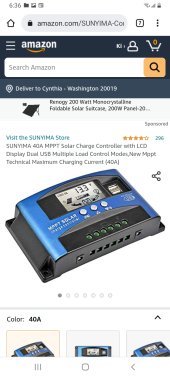
Just to make things more confusing, the solar controller you chose is not a true MPPT, the performance with the selected panels will be poor. It will harvest a theoretical max of 16 amps, a MPPT will give more than twice that.
Here is an example of MPPT......
Here is an example of MPPT......
Similar threads
- Replies
- 5
- Views
- 346
- Replies
- 5
- Views
- 206
- Replies
- 9
- Views
- 300
- Replies
- 7
- Views
- 409