diy solar

diy solar

Solar String Configuration w Safety Margin to Remain Below Voc

bob.longmire

New Member
Joined
Jun 25, 2022
Messages
49
Is there any recommended safety margin or factor when remaining below Voc on solar string input?

I have 10 panels with a Open-Circuit Voltage of 49.35. My EG4-6500 inverter has a max Open-Circuit Voltage of 500 Volts.

My 10 panels would have a max Voc of 493.5 Volts.

That's so close to my 500 V max threshold, it's a little worrisome as I live in a hot, desert climate where we're pushing the maximum temps seen on Earth.

Should I be worried? Would you be?

Should I setup 2 strings in parallel made up of 5 panels in series? That'd give me 250 V VOC and around 15 AMPs each and us a Y-Combiner to connect the 2 strings?

Thanks!
 
What’s the minimum Vin for the MPPT?

Going with a lower voltage of 5s2p how does that impact your conductors?

I have to imagine Isc is close to 10-15a, so you’re not looking for slightly larger conductor. I’d try and keep away from pushing 30a through an MC4 or #10awg.
 
I'm using the EG4-6500 inverters as my charge controller. The Inverter has an max Input current of 18 AMPs (on each MPPT Input) and a max 500 V Open Circuit for the array.

I'm using the Solarever 455 W panels with 49.35 V Open Circuit and 10.96 Maximum Power Current per panel. Note, each panel has a fuse for 20 AMPs.

With 9 panels connected, I'm putting out 10.2 Amps and with 5 panels connected I'm putting out 9.9 Amps.

So, if I doubled my amperage, I'd exceed my max input current draw amperage of 18 amps.

Thanks!
 
Minimum voltage is 70 Volts.

I have 2 inverters and 20 total panels. Each inverter has 2 MPPTs.

I'm trying to avoid using both inputs to minimize the wire run from the array to the inverters.

But, worse case, I could run 4 strings of 5 panels across 4 MPPT inputs. I'd just need to run some additional wires from the array to the inverters.
 
My 10 panels would have a max Voc of 493.5 Volts.

That's so close to my 500 V max threshold, it's a little worrisome as I live in a hot, desert climate where we're pushing the maximum temps seen on Earth.

The question is not how hot it gets, but how cold. What is the record coldest temperature?
What is the Temperature coefficient of Voc from PV panel data sheet?

If it ever gets below 23 degrees C, that 6.5V margin won't be enough.
 
Thank you! I didn't realize that cold caused Voc to increase. I see the graph of Voc change by temp for my panels now.

If I plan for -2 Celsius that is our record cold.

At 0 C that graph looks like 108% of Voc. So, let's call it 110% of Voc (that absolutely tells me I shouldn't put 10 panels together as that would for sure exceed the 6.5V margin).

A 110% Increase in VOC, for 9 panels, that would be 488 Volts Voc which would only give me a 12 volt (or 2.5% safety factor) . So, 9 panels in a string would be the max and that would risk a super cold, sunny day putting me over my VOC. Now, that probably won't happen, but 9 could be risky in that setting.

If I create 2 strings of 5, is that better than 1 string of 8 and 1 string of 2? When creating a string, do both legs of that srting need to be equal? So, with 10 panels that are all the same, do I want 2 strings of 5, or can I mix and match based on what's easiest to wire?

Thanks!
 
If strings are to be put in parallel to a single charge controller. Then they need to be the same. 5s2p is the way to go. For the 10 panels you have.
 
Thank you! I didn't realize that cold caused Voc to increase. I see the graph of Voc change by temp for my panels now.


If I create 2 strings of 5, is that better than 1 string of 8 and 1 string of 2? When creating a string, do both legs of that srting need to be equal? So, with 10 panels that are all the same, do I want 2 strings of 5, or can I mix and match based on what's easiest to wire?

Thanks!
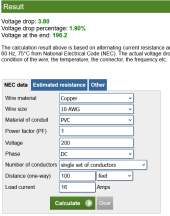
Parallel strings always need to be the same voltage. Here is what 5 of your panels in series looks like in a voltage drop calculator. In this case, I used a Vmp of ~40V, not the Voc of 49.35V. So, what you can see is that at a 100' distance, you lose less than 2% of your power. 3% is considered to be the acceptable limit. How far away from your electronics will be panels actually be placed? You can plug your own numbers into the calculator, but at the distance I estimated, two parallel strings of 5 panels looks just fine. https://www.calculator.net/voltage-drop-calculator.html
1677602872833.png
 
Hi Mike,

The good news is panels are on the roof and inverter is 20 feet away, so losses are minimum and wire costs are small. But, I'd like to combine both strings on the same 10 gauge line as I already have the roof pentation and lightning shunt setup. So, the easiest solution would be to use the existing line and add a y combiner to link the 2 strings of 5 together right before it goes to the shunt and through the roof.

This will solve my VOC problem, but it may introduce an amperage problem. my panels have a 20 AMP fuse and I'm at 10.96 AMPs on the current string. So, putting both strings on the same line may trip the breakers in my panels.

Any thoughts on putting both strings on the same line through the roof? Does my amperage only apply AFTER the Y combiner? So, I'd have 10 AMPs on each of my 5 panel strings, then AFTER I combine them, before going through the roof, the line would jump to 20 AMPS? Or, does it complete the circuit and my 5 panel strings would then have 20 AMPS across all panels? Not sure how that works.

Thanks!
 
Does my amperage only apply AFTER the Y combiner? So, I'd have 10 AMPs on each of my 5 panel strings, then AFTER I combine them, before going through the roof, the line would jump to 20 AMPS? Or, does it complete the circuit and my 5 panel strings would then have 20 AMPS across all panels? Not sure how that works

Have you actually measured the amperage flowing through the wires, or are you only looking at panel specifications? The reality is that you may never see the rated amperage flowing out of your panels. I typically de-rate panel output by 85% for realistic real-world production.

To answer the question above, each string has it's own amperage. The amperages add in parallel, so the 10.96A +10.96A occurs before & after the Y-connector. So the combined strings would theorically be 21.92A.
 
What is the amperage rating for your SCC?
That's the most the wires will see.
This will limit the amperage and probably keep it below the fuse rating.
 
The EG4-6500 inverter has an amperage limit of 18 AMPs.

Right now, the display on the inverter says with 9 panels connected, I'm pulling in 10.2 Amps and with 5 panels connected I'm pulling in 9.9 Amps.
 
Wire after paralleling should be sized for Isc x 1.56, which per code might even be 8 awg not 10 awg.
20A fuse is also not sufficient, should be sized similarly. But no fuse needed for two strings in parallel.

If the two strings are different orientation, that will reduce peak. I like SW and SE orientation, for more flat power production during the day.

Is there a maximum short-circuit current spec for the EG4?
 
Hmmm, I can't find a short circuit current spec. All my panels are on the same roof facing the same direction, so we should be good there.
 
500V max, MPPT operation 90 to 450V
18A Max Input Current Draw


18A x 2 max input current draw


Maybe OK for 18A Imp, a bit higher Isc? They aren't explicit.
One reason for short-circuit current limit is, if PV array connected backwards, some inverters have reverse polarity protection diode that has to carry the current. (those which don't may get killed in up to 50% of installations.) Check polarity before closing breakers.

We would hope inverter would never draw enough current to hurt itself, but that is under firmware control.
Some may even protect against over-voltage by crowbarring PV input with FET.

I'm using the Solarever 455 W panels with 49.35 V Open Circuit and 10.96 Maximum Power Current per panel. Note, each panel has a fuse for 20 AMPs.

Should I setup 2 strings in parallel made up of 5 panels in series? That'd give me 250 V VOC and around 15 AMPs each and us a Y-Combiner to connect the 2 strings?

2 x 10.96 would give 22A Imp
15A ? I see 11.44A Isc


Assuming the inverter doesn't mind higher Isc, it will limit to 18A under best conditions, over-paneled with current so maintain 18A so long as illumination is at least 80% of full sun. If the two strings were different orientation then it could capture more. But panels are fairly inexpensive ($0.50/W) so you mount them however they fit.
 
Back
Top