diy solar

diy solar

Solark inverter - flickering lights

All modern inverters using PWM digital sinewave creation have an output L-C filter to smooth out the PWM chopping to a pure sinewave.

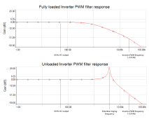
The L-C filter has a typical cutoff corner frequency between 2 kHz to 4 kHz. When inverter is lightly loaded the L-C filter becomes very undamped which makes it vulnerable to ringing near the filter's cutoff frequency. Impulse current loads like simple rectifier-filter power supplies that draw short bursts of current at the peak voltage of AC sinewave, can set the L-C filter ringing. This is AC loads with high current crest factors and poor power factors.
Inverter PWM filter response.png

The L-C filter ringing can upset the inverter's AC voltage feedback regulation causing it to become unstable on holding its AC output voltage regulation. Result of the unstable AC voltage regulation is the flickering of lights as the inverter's AC output voltage varies at a high rate.

The only way to control the ringing is with snubber circuits that clamps the ringing reducing its severity. Too much snubbing to dampen ringing adds idle current to inverter so it is a compromise in the amount of dampening versus additional idle current. Also, the inverter AC output feedback control can filter some of ringing so the perturbing effects on AC voltage regulation is reduced. Again, there is a compromise on the AC voltage feedback filtering to remove ringing as it slows down response reaction time to surge current loads on inverter. The second part (feedback regulation filtering) is the only thing that can be tweaked by inverter firmware.

Best thing you can do is to try and avoid loads with high current crest factor, simple rectifier-filter capacitor power supplies.

Cheap mini-split air conditioners, for U.S. market that for most U.S. states do not regulate appliance power factor, use simple rectifier-filter capacitor power supplies to create the HV DC for their high frequency variable speed three-phase inverter to drive compressor and variable speed fans.

Mitusbish mini-splits have electronic power factor correction. They are one of the few manufacturers that actually spec their power factor. They are very good in the 98% range.
Mitsubishi MXZ-2C20NA3 power factor spec.png

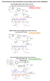
Full Wave rectified Power Factor diagram.png
 
Last edited:
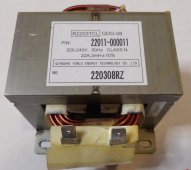
On larger btu mini-splits, because their peak current at sinewave voltage peaks is so great, the units usually have a filter choke in the rectifier-filter power supply to reduce the peak current. It is not as good as an electronic power factor correcting power supply, but it does reduce the peak AC load current by about half. It improves their power factor to about 0.75.

It is the AC load impulse current spikes that sets off the inverter's L-C filter ringing. Like plucking a string on a guitar.

Mini Split AC PF choke.jpg
 
Last edited:
All modern inverters using PWM digital sinewave creation have an output L-C filter to smooth out the PWM chopping to a pure sinewave.

The L-C filter has a typical cutoff corner frequency between 2 kHz to 4 kHz. When inverter is lightly loaded the L-C filter becomes very undamped which makes it vulnerable to ringing near the filter's cutoff frequency. Impulse current loads like simple rectifier-filter power supplies that draw short bursts of current at the peak voltage of AC sinewave, can set the L-C filter ringing. This is AC loads with high current crest factors and poor power factors.

The L-C filter ringing can upset the inverter's AC voltage feedback regulation causing it to become unstable on holding its AC output voltage regulation. Result of the unstable AC voltage regulation is the flickering of lights as the inverter's AC output voltage varies at a high rate.

The only way to control the ringing is with snubber circuits that clamps the ringing reducing its severity. Too much snubbing to dampen ringing adds idle current to inverter so it is a compromise in the amount of dampening versus additional idle current. Also, the inverter AC output feedback control can filter some of ringing so the perturbing effects on AC voltage regulation is reduced. Again, there is a compromise on the AC voltage feedback filtering to remove ringing as it slows down response reaction time to surge current loads on inverter. The second part (feedback regulation filtering) is the only thing that can be tweaked by inverter firmware.

Best thing you can do is to try and avoid loads with high current crest factor, simple rectifier-filter capacitor power supplies.

Cheap mini-split air conditioners, for U.S. market that for most states do not regulate appliance power factor, use simple rectifier-filter capacitor power supplies to create the HV DC for their high frequency variable speed three-phase inverter to drive compressor and variable speed fans.

View attachment 152416
 
When inverter is lightly loaded the L-C filter becomes very undamped which makes it vulnerable to ringing near the filter's cutoff frequency.
Makes sense.
And I appreciate your detailed comment on this.

There was a time I noticed that the pulsating lights "stopped" pulsating while the well pump was in operation. The well pump is 240V jet pump and draws about 3-4 amps when touching up the water system pressure.

What I also see is an issue when I have a Dell laptop charger plugged in and the charger appears to be topping off the laptop battery . There's a blink, or flicker, or twinkle..... as I would describe it, not like in a rhythm of frequency (like 60hz). It amazes me that something of such small current draw can cause a feedback into the system to make a noticeable variation in the lighting.

40 years ago I was stronger with finer electronics and have a DOD defense budget at my fingertips and might be crazy enough to build a new power supply for that mini-split..... but laughable that I'm not in such situation today.
 
There are two common types of poor power factor, high crest factor loads and reactive loads. AC motors are inductive with sinewave current profile lagging in time of the sinewave voltage profile. An inductive motor load effectively cancels out some of the L-C filter output capacitor value, raising the corner frequency of PWM filter. This higher ringing frequency can then be attenuated to a greater degree by inverter's voltage feedback loop filter.

The more real (non-reactive, non-impulsed) the load, the more dampened the inverter's L-C filter and the less ringing.

If you put enough resistive load on inverter, like a heating appliance, the ringing will reduce or stop.
 
Last edited:
If you put enough resistive load on inverter, like a heating appliance, the ringing will reduce or stop.
That makes sense....and I proved this.
also, in the absence of a ( load balancing) auto-transformer....( as in my case).... adding load specifically to the same leg, will reduce or stop the ringing.

also,
I re-visited the idea of switching out the LED lamps to non-dimmable (as someone else suggested) - but with careful testing, use of non-dimmable bulbs in my application was not a solution. Incandescents didn't seem to eliminate the effect, but were maybe slightly less noticable than the LED's.
 
I've decided to get a 12v DC E27 lamp (ebay 363861186585) and a constant current / constant voltage module (ebay 354644927748) for a dimmable light.
I will put the module in its own box, give it a DC input socket and replace the constant current trimpot with a panel mount one (ebay 191864936180).
I've tested this particular module and it does go down to 0 current. (Some modules only go down to 0.4A or 0.7A).
I'm using a floor lamp so will put a mains socket on the box so that the lamp can simply plug into the box (ebay 203530477726).
 
All modern inverters using PWM digital sinewave creation have an output L-C filter to smooth out the PWM chopping to a pure sinewave.

The L-C filter has a typical cutoff corner frequency between 2 kHz to 4 kHz. When inverter is lightly loaded the L-C filter becomes very undamped which makes it vulnerable to ringing near the filter's cutoff frequency. Impulse current loads like simple rectifier-filter power supplies that draw short bursts of current at the peak voltage of AC sinewave, can set the L-C filter ringing. This is AC loads with high current crest factors and poor power factors.
View attachment 152437

The L-C filter ringing can upset the inverter's AC voltage feedback regulation causing it to become unstable on holding its AC output voltage regulation. Result of the unstable AC voltage regulation is the flickering of lights as the inverter's AC output voltage varies at a high rate.

The only way to control the ringing is with snubber circuits that clamps the ringing reducing its severity. Too much snubbing to dampen ringing adds idle current to inverter so it is a compromise in the amount of dampening versus additional idle current. Also, the inverter AC output feedback control can filter some of ringing so the perturbing effects on AC voltage regulation is reduced. Again, there is a compromise on the AC voltage feedback filtering to remove ringing as it slows down response reaction time to surge current loads on inverter. The second part (feedback regulation filtering) is the only thing that can be tweaked by inverter firmware.

Best thing you can do is to try and avoid loads with high current crest factor, simple rectifier-filter capacitor power supplies.

Cheap mini-split air conditioners, for U.S. market that for most states do not regulate appliance power factor, use simple rectifier-filter capacitor power supplies to create the HV DC for their high frequency variable speed three-phase inverter to drive compressor and variable speed fans.

View attachment 152416
This look exactly like what is happening with both my 2 split phase LV6548 inverters. I have 2 small AC units (1300w) and one larger 240v unit (2500w) that cause the problem when they are all on. And as the AC output degrades on the inverter that has the highest load (down 10v from the other), the PV production drops to almost nothing on that inverter. Load balancing just moves the problem to the opposite inverter.


I'm going to try adding an RC snubber filter with 2.5uf/10ohm on each leg once I get the right caps delivered. I'll also try adding a resistive heater to the leg that's failing to see if I can reduce the ringing on that leg.
 
Last edited:
I realize I'm late to this thread, but I found it very enlightening. Early on, from the problem descriptions, I was intuiting that the problem had to do with power-factor issues. But I know little about power factor. Years ago, I enrolled in a distance-learning electronics course from CIE that would have given me a very nice certificate/degree if I had completed it. I moved out of country before completion, and had found myself bogged down with the math (I struggle to understand complex math). But having completed a number of the units in that course, I have at least some idea of what power factor is. @RCinFLA's explanation was awesome.

I'm now thinking I'm quite fortunate to have chosen an LF, toroidal inverter (which has arrived but is not yet installed). From what I understand, it should not have any of these issues. I would like to consult this thread again if, after installation, I notice any of these pesky flickers.

EDIT: I should add, I have purchased an LVTOPSUN inverter, which, if I am not mistaken, is made by the same company which makes the Sol Ark. I have found several names which seem linked to this same company: Deye, Pylon, LVTOPSUN, and Sol-Ark. Perhaps there are others as well.
 
Back
Top