diy solar

diy solar

[Solved] Growatt Parallel and Error 03

emmantsia

New Member
Joined
Jul 1, 2022
Messages
6
Hello guys,
I have a parallel setup of 3xHybrid Growatt Inverters.

Specially the setup is:
Battery: 16 x 250Ah Lead Acid Batteries (Closed type - deep cycle). 4 in series and 4 parallels. Total 1000Ah / 48Kwh.
Inverters: 3 x SPF 5000 ES (3 Phase Parallel Setup)
Solar: 18 x 550 Watt EP Solar. 3 strings x 6 Panels. 3300Watt/per string - invereter.

Settings:
Battery type: USE (User Defined)
A.C. Voltage: 57.6v (Battery label shows 14.4 x 4 = 57.6)
Floating Voltage: 54.8v
Back To Grid: 44v
Cut-Off: 42v
Priority: SBU (Solar Battery Utility)
Charger: OSO (Only Solar)
Charger Amp: (60A Total + 30 Utility)

The strange of this system, is the system increase the voltage to limit (60v) and shows error 03 (Voltage to High). Of course is turning off everything.
As i see in the current time on multimeter the voltage is the same with inverter reading. If i turn off the batteries and restart again after 2 hours (for example) it shows me 52+v. (Not fully charged).
It is very strage that. Why it will be happening this?
This is a new setup. We tried again with 2Vx24 Open Lead Acid batteries with same results.
Battery Cables are 50mm Copper and not more than 2.5m

Other 2 systems that we have with similar setup but other brand (Alpha & Outback energy) they haven't any problem. And with the same type battery, same software on inverter and same settings.

Maybe is something strage with growatt inverters?

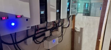
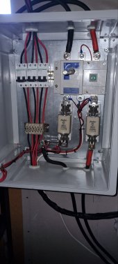
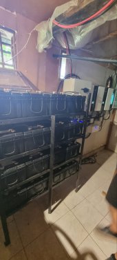
Photos Attached:
viber_image_2022-06-30_15-26-26-320.jpg

viber_image_2022-06-30_15-26-26-555.jpg
viber_image_2022-06-30_15-26-26-701.jpg
 
Settings:
Battery type: USE (User Defined)

Did you try FLD (flooded)?
Same and more bad Result.
FLD has C.V. 58.4v predefined and make the situation worst.
For 1000Ah battery the 0.2C is 200Ah charging and i have the chargers to max (60A) ... tha means total max 3 x 60A = 180A that is better for battery. I tried also 50A per inverter.

Thanks.
 
Same and more bad Result.
FLD has C.V. 58.4v predefined and make the situation worst.

That would be 14.6V for a 12V FLA battery. You have to remember 2 things with lead acid batteries, one, the internal resistance increases as SOC charge increases. LFP on the other hand does not see any noticeable increase in internal resistance. Lead acid will require a higher charge voltage to push in current as the internal resistance increases. 14.6V on a 12V lead acid battery would be considered normal charge voltage.

Second, lead acid requires absorption to reach full charge. This is due to the internal resistance mentioned above. Current will be lower and it will take time to achieve full SOC.

For 1000Ah battery the 0.2C is 200Ah charging and i have the chargers to max (60A) ... tha means total max 3 x 60A = 180A that is better for battery. I tried also 50A per inverter.

Thanks.
Have you checked the voltage of each battery? And each parallel bank compared to others? What is the battery cable routing for both series and parallel?

You could reduce charging even lower. In your original post you wrote "Charger Amp: (60A Total + 30 Utility)" so I have to wonder if this isn't 90A times 3 units.
 
That would be 14.6V for a 12V FLA battery. You have to remember 2 things with lead acid batteries, one, the internal resistance increases as SOC charge increases. LFP on the other hand does not see any noticeable increase in internal resistance. Lead acid will require a higher charge voltage to push in current as the internal resistance increases. 14.6V on a 12V lead acid battery would be considered normal charge voltage.

Second, lead acid requires absorption to reach full charge. This is due to the internal resistance mentioned above. Current will be lower and it will take time to achieve full SOC.


Have you checked the voltage of each battery? And each parallel bank compared to others? What is the battery cable routing for both series and parallel?

You could reduce charging even lower. In your original post you wrote "Charger Amp: (60A Total + 30 Utility)" so I have to wonder if this isn't 90A times 3 units.

Hello,
and thanks for any information.

About the batteries:
Brand: Mitsuba
Type: Lead Acid / Closed type / Deep Cycle for solar (Non AGM or GEL)
Capacity: C100 250Ah / C20 235Ah
Voltage: 12V
Charging: 13.8V - 14.4V
Connection: 4 in series (48V) and 4 in parallel (Total 16 batteries)
Cabling: All cables are 50mm Coper. The bridges are 30cm length (series) and 50cm length (parallel). From batteries to inverters is 2.5m total.

I was made an equalize after the first charging and today i check the voltage when the batteries was on floating voltage (54.8V). All bateries has same voltage (13.70V - 13.73V).
About the Charger is set to 60A (Total). Not 60+30 = 90A. But as i see the Ameter shows about 60-70A max to battery and not 180A that i was thinking.

Today i saw more specific the problem.
How to produce the error 03:
- System was on floating voltage (54.8V) and the requested total power it was about 1.5Kw
- When i turn on a huge device like 3-4Kw (Boiler) system is working properly.
- When i ask for 4K from the first inverter i saw that 2.3kw is getted from Solar Panels, the rest 1.7Kw it was getted from Solar panel of the second inverter and some extra kW from the 2nd and 3rd inverter for the rest devices.
- On this time that the boiler is working, the inverters are started to charging the battery to 57.6V. All ok until here.
- When i turn off the Boiler (4kW) then the battery grow up to 60+ Voltage and the system produce the error 03. In this time it goes to 60+V for 2-3 Second, drops down to 57.6 for 2-3 second and again 60+ for few seconds and this repeated 2-3 times before it goes back to stable 57.6V.
If we are lucky and the overvoltage is about 2-3 Second per time the system doesn't closing. But if is keeping for 1-2 seconds more then the system is cutting-off.

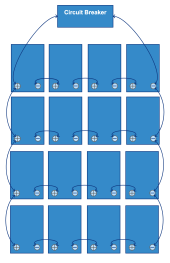
The battery setup is:
Screenshot 2022-07-02 at 19.15.07.png

I'm thinking to try 2 more thinks:
1) Reduce the bulk charging voltage from 57.6V to 56.4V. Maybe this peak will be unter the 60V and don't have problems.
2) If you see the sketch above the +/- connectors are on the first series of batteries. I'm thinking to keep the positive to the first series and the negative to the last series of batteries.
It sounds good that to test it?
Something else?

Thanks again.
 
Last edited:
Hello,
and thanks for any information.

About the batteries:
Brand: Mitsuba
Type: Lead Acid / Closed type / Deep Cycle for solar (Non AGM or GEL)
Capacity: C100 250Ah / C20 235Ah
Voltage: 12V
Charging: 13.8V - 14.4V
Connection: 4 in series (48V) and 4 in parallel (Total 16 batteries)
Cabling: All cables are 50mm Coper. The bridges are 30cm length (series) and 50cm length (parallel). From batteries to inverters is 2.5m total.

I was made an equalize after the first charging and today i check the voltage when the batteries was on floating voltage (54.8V). All bateries has same voltage (13.70V - 13.73V).
About the Charger is set to 60A (Total). Not 60+30 = 90A. But as i see the Ameter shows about 60-70A max to battery and not 180A that i was thinking.

Today i saw more specific the problem.
How to produce the error 03:
- System was on floating voltage (54.8V) and the requested total power it was about 1.5Kw
- When i turn on a huge device like 3-4Kw (Boiler) system is working properly.
- When i ask for 4K from the first inverter i saw that 2.3kw is getted from Solar Panels, the rest 1.7Kw it was getted from Solar panel of the second inverter and some extra kW from the 2nd and 3rd inverter for the rest devices.
- On this time that the boiler is working, the inverters are started to charging the battery to 57.6V. All ok until here.
- When i turn off the Boiler (4kW) then the battery grow up to 60+ Voltage and the system produce the error 03. In this time it goes to 60+V for 2-3 Second, drops down to 57.6 for 2-3 second and again 60+ for few seconds and this repeated 2-3 times before it goes back to stable 57.6V.
If we are lucky and the overvoltage is about 2-3 Second per time the system doesn't closing. But if is keeping for 1-2 seconds more then the system is cutting-off.

Looks to be a transient spike from a large load. SCC is putting out high watts, then the sudden switch off and it can't correct fast enough.


That is a problem and most likely the cause of the transient spike. The upper first bank will overcharge and the lower bank will be a lower voltage. Preferably the taps would be in the center of the banks shown in the bottom diagram of this webpage under Perfectly Balanced Charging. https://www.impactbattery.com/blog/post/how-to-charge-marine-and-rv-batteries-in-parallel

In your case, it would be slightly different but the concepts are the same. Each bank of 4 batteries would be wired this way, then each bank would be the same concept.

Currently, even though you think you are charging at a low C rate for the entire pack, the problem is the first row of batteries will be charging at a much higher C rate and the last row. This is also shortening your battery life.
I'm thinking to try 2 more thinks:
1) Reduce the bulk charging voltage from 57.6V to 56.4V. Maybe this peak will be unter the 60V and don't have problems.
2) If you see the sketch above the +/- connectors are on the first series of batteries. I'm thinking to keep the positive to the first series and the negative to the last series of batteries.
It sounds good that to test it?
Something else?

Thanks again.
 
Looks to be a transient spike from a large load. SCC is putting out high watts, then the sudden switch off and it can't correct fast enough.


That is a problem and most likely the cause of the transient spike. The upper first bank will overcharge and the lower bank will be a lower voltage. Preferably the taps would be in the center of the banks shown in the bottom diagram of this webpage under Perfectly Balanced Charging. https://www.impactbattery.com/blog/post/how-to-charge-marine-and-rv-batteries-in-parallel

In your case, it would be slightly different but the concepts are the same. Each bank of 4 batteries would be wired this way, then each bank would be the same concept.

Currently, even though you think you are charging at a low C rate for the entire pack, the problem is the first row of batteries will be charging at a much higher C rate and the last row. This is also shortening your battery life.

Thanks for the TIP.
My first think that i want to try is too close to perfect balanced, but now i will try direct the perfectly balanced connection.
I will make only that change and i will see if that make any voltage peak again.

Thank you again, and i will return back with information.
 
Looks to be a transient spike from a large load. SCC is putting out high watts, then the sudden switch off and it can't correct fast enough.


That is a problem and most likely the cause of the transient spike. The upper first bank will overcharge and the lower bank will be a lower voltage. Preferably the taps would be in the center of the banks shown in the bottom diagram of this webpage under Perfectly Balanced Charging. https://www.impactbattery.com/blog/post/how-to-charge-marine-and-rv-batteries-in-parallel

In your case, it would be slightly different but the concepts are the same. Each bank of 4 batteries would be wired this way, then each bank would be the same concept.

Currently, even though you think you are charging at a low C rate for the entire pack, the problem is the first row of batteries will be charging at a much higher C rate and the last row. This is also shortening your battery life.

Hello!
I made he change to connection of batteries for the "perfect" balancing.
All batteries had total 54v from each compination of stucks that i put the meter and each battery has 13.498 - 13.516. Most of them had 13.50 exactly.

I was made a test again with large load.
With C.V. 57.6V it goes to 60.2V peak but the system didn't closed.
I Change C.V. to 58.4V and after larg load system closed.

I made another test. I change the charging controllers to 30A (From 60A).
With this setting and C.V 58.4V didn't closed. Also i tried again with load of 6kW total without problem.
Now i'm waiting to make a final test after the charging stops and the battery is 100%. At this time is on floating charging with 60A charging Current! and 55.2V.

I will return back again, with final test information.
Thank you!
 
  • Like
Reactions: Zwy
Finally, i think the problem is gone.
I made bellow tests with large load and C.V. 58.4:
- Battery on Bulk Charging and reached 100%
- Battery full on floating voltage
- Battery 75% at night without panels
Every test goes perfect. Now the system is not closing with error 03.

The final settings at the moment are:
C.V.: 58.4V
Floating Voltage: 54.8V
Charging Current: 30A
Return to battery: 54V
Return to Grid: 48V
Cut-off: 44V
Priortiy: SBU
Charging: OSO
And of course the perfect balancing like Zwy suggest.

With normal usage of the house the battery on the morning before begin the charging it has 50.7V.
Also is saw that 30A is per inverter. I saw that because i see the Ameter to give 87A to the battery.
That means, total 90A from all inverter is the 0.1C of battery charging. I think is good. Normal is 0.2C and slow 0.05C.

Conclusion: For the Growatt inverters and Lead Acid Batteries the most important is the charging current.

Thanks again for any help and tips!
 
  • Like
Reactions: Zwy
Back
Top