diy solar

diy solar

[solved]WARNING. here be dragons. Stress testing a single cell with a DIY transformer

yes

yes.
I am assuming 230VAC. As the variac is maxed out and the analog display dangles around 230V.
Should I confirm this?

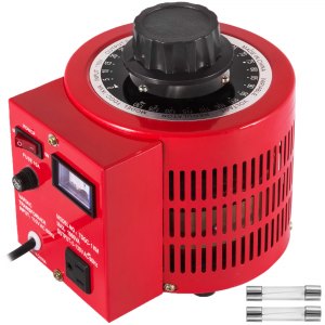
I'm curious. 2000VA on primary of variac, 240VA on secondary. What happened? I didn't expect Variac to inductively store that power between phases. Seems odd.

Can you please elaborate?

Back in the days of vacuum tubes, transformers put out high voltages for grid, and 6.3VAC for vacuum tube filament.
I often used scrap transformers for TTL supplies (high voltage windings carefully taped off.)

Ok, i'll use the variac then to slowly increase the power to the battery cell while measuring voltage and amps going into the cell.


hahahha ;) I am afraid I do not have time for an extra project ;(


Do you mean not use the current power socket to feed the variac but use a regulated power source?

No, I mean use what you've got for 140A charger up to a high-voltage disconnect you design. Open a relay to turn off AC to the variac (or DIY transformer) at that point.

You've completed 140A CC.

For CV, use an off-the-shelf maybe 10A power supply for remaining CV portion. It will probably sit at CC 10A for a while, then switch to CV.
Topping off lithium should be done carefully.
The guys here with lithium experience wouldn't use your home-brew arc welder to top-balance cells. Reliable regulation is important.

I'll read up on that to see if I will be worried about that

I imagine current and voltage will go up and down quite a bit. Not like a normal regulated bench supply. More like what an AC coupled battery inverter like my Sunny Island does.
 
i think I understand now. I never meant to hook up AC to a DC cell. I plan to use a rectiifier and maybe also a capacitor just before the cell

Rectifier of course. Then you've got DC going to zero, up to a peak and back down.
Capacitor is a start. But you'll never have enough capacitance to smooth out that 140A, 50 Hz ripple.
Maybe a series inductor would help. It would have to be big enough to store the energy. But it could overshoot, drive current through any switch on the DC side with high "inductive kick" voltage.
Only way I can see regulating is to have higher voltage on a capacitor, allowed to ripple as a linear regulator drops voltage to CV/CC output.
Or high frequency switcher. It also needs filtering, but at 50 kHz it needs 1/1000 as much.

A 3-phase source helps alleviate filter needed for rectifier/capacitor front end.
For high-frequency switcher, it can be near perfect; 3-phase delivers constant power (to a "real" load), same as DC.
 
3-phase source
I can route a 3 phase connection to my workbench. It will require though to make 2 extra transformers.

I already have a 3phase full bridge rectifier that can take a beating on paper. But I have not tested this one yet and had to send a single phase recitifer from a different manufacturer back because was not up to specs.

I will consider going 3 phase early in the process rather than later as I will need to do that anyway because once I have confirmed these cells to be up to specs I will use these transformers to convert a 3 phase output from a DIY wind turbine generator to 48VDC. And since I'll need 3 transformers for that anyway I might as well do that now to help smooth out the ripple for charging the cells.
 
Last edited:
A basic unregulated battery charger is just transformer and rectifier. With a spring-wound timer it can be automatically shut off.
Better chargers would be CV/CC.

Variac is going to be difficult to set accurately between 2V and 3V for a single cell. Using a step down transformer after it would give finer voltage control and more current.
FLA batteries normally want about 0.12C charge rate. To equalize, fully charge to normal voltage and then charge to elevated voltage for a period of time. To equalize my old AGM (maybe 40 Ah car battery) I charged to 14.5V with 1A bench supply, then added 8 hours at 15.5V. Find a manual for your cells or similar.
 
uggg ;( while mentally preparing the routing of a 3 phase power source to my workbench I realized that I only have a single phase variac.

How to proceed?
 
or maybe just start treating this a bit more adventurous and cut out the variac and get on with the big guns.

But then I am still not sure on how to set a cap at 140 amps.
 
Only way I can see regulating is to have higher voltage on a capacitor, allowed to ripple as a linear regulator drops voltage to CV/CC output.
Similar to what I proposed in the beginning. 14 10A CC/CV step down modules in parallel should produce 140A in CC/CV mode. There are other issues that should be considered with that approach, but still - you can put a cap on the voltage and the current. And such modules are cheap on Aliexpress.
 
Back
Top