diy solar

diy solar

[solved]WARNING. here be dragons. Stress testing a single cell with a DIY transformer

cool video. I am not understanding it yet though. Anyway I am not going to use ferrite as this is not a high frequency applicaiton. I am going to use iron powder.
 
What is the magnetic permeability of the powder?
I'm not sure of where "iron powder" fits into the definition of "ferrite" or "steel core", but I think it is a high-frequency ferrite.
Various steel alloys are used for cores. Silicon steel is used for at least some (relatively) low-loss toroids, also other low-frequency applications.

You should use a coil around sample of core (maybe a core that forms a complete magnetic circuit, e.g. inside a plastic pipe to make an "O" shape), and use variac (probably together with step-down isolation transformer) and come up with BH curve, see how much voltage/current to saturate. I think the iron powder core won't handle nearly as much as laminated steel. It could be a good fit for high-frequency switcher, but not 50/60 Hz low-frequency.

For higher frequency applications, different ferrites are used for different frequency ranges, to get the best loss and perhaps other characteristics.
I used an "iron powder" ferrite for an 11 MHz RF application, an analytical instrument. Relative permeability was just 8.


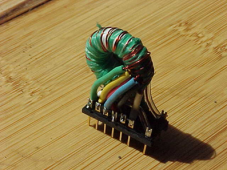
An early attempt, with "enamel" magnet wire and multiple taps.
Problems were high capacitance due to thin insulation, and extra turns for the multiple taps, which lowered resonant frequency excessively (below intended operating frequency.)

1645378299970.png

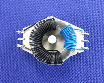
Production, using "Kynar" wire-wrap wire which has about 10 mil thick insulation:

1645378698110.png
 
What is the magnetic permeability of the powder?
I am not sure how to measure that. I've spend an hour or so reading up and searching and found nothing I understand or I find only things that seem inconsistent.

The powder I have is almost pure iron (>99% FE, 0.05% carbon, 0.6% Oxygen)
I am beginning to suspect that it is not ferrite and that it can be used in this application although not super efficient. But that is ok.
 
It is related to the ratio of coil inductance with/without core. I'm not sure if core geometry (cross-section area & centerline length) are part of the equation.

I hate Greek letters (except the one used for "ohms"). They make it so hard to solve equations.


Working with those -6 ferrite cores above, I started with data sheet indicating a particular inductance for a particular number of turns, and calculated assuming inductance goes as square of turns. It was far from that, due to low permeability not confining magnetic field so it passed through all other coils. I ended up designing it empirically.

In the video I linked a few posts back, he showed how current through coil (fed by AC) decreased when he inserted core material. But most of the magnetic circuit path length was still through air; he only shorted a fraction of it with core material. So only a bit of difference between steel and ferrite.


What I'm doing is described in the EEVblog link:


After reviewing the equations implemented with LTSpice parameterized components such as voltage controlled current source, I figured out how to take data points from the hysteresis curve (generated with variac, integrator, scope), which had mA on x-axis & mW on y-axis, and convert them to Hc, Br, Bs. Then I was able to simulate in LTSpice and get a hysteresis curve that was similar (but not a perfect match.)


The following link puts relative permeability
{\displaystyle \mu _{\mathrm {r} }={\frac {\mu }{\mu _{0}}},}
of pure iron at 200,000 but iron powder compound at 14 to 100.

 
My latest experiment and what was posted above crossed each other so I'll make sure to read up.


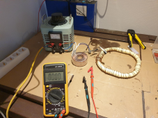
While I am waiting for the isolating transformer to arrive I figured to use a torodail transformer in the mean time as I assumed it is also isolating.

I am not sure how many volts went in (variac dial at 25%) but I was able to measure about 150 milli VAC coming out of the torodial transformer.

So I hooked up a pipe filled with iron powder which I sloppyly coiled up with only a primary coil for now.

However the experiment tripped the circuit breaker again ;(

Any suggestions on how to proceed are welcome.

1645448813895.png
 
You can use an ohm meter to see if coils of a transformer are isolated. Usually, each coil is isolated from others and has two leads. External to the windings, two coils might be connected in series, or in parallel (need to be same number of turns). Occasionally, two windings might already be connected in series with just 3 leads coming out.

Without anything connected to toroid transformer, measuring voltage in and out gives ratio of turns.

In the guy's video, with a 12V transformer, he connected a 12V car head lamp in series. That way if your DUT (device under test) doesn't have enough impedance to keep current low enough, voltage drops across the lamp and maximum current is what the lamp would draw.

The variacs I've seen go some percentage above input voltage. Yours has a meter up to 300V. 25% would be 75V from variac into toroid. You haven't indicated what voltage ratio toroid has. Open-circuit, that is. "150 mV" is its output pulled down with the short circuit loading it.

Your DUT has a coil diameter (about 2.5 cm) and number of turns (about 100?). Loosely space, so without core most magnetic field would leak out. You could calculate inductance assuming a uniform solenoid. Calculate AC impedance (reactance) at 50 Hz. Calculate current vs. voltage.

Measured with/without core material should give an indication of relative permeability.
Without a plumbing "T" to fill from, I would imagine there are airgaps without powder. But that probably isn't the biggest problem, rather the relative permeability being low.

It seems annealing is performed on magnetic material after they are formed. We've go some quotes for Mu-metal shields, which are to be formed by drawing or welding, then annealed. Working metal or sudden cooling results in small grains. Annealing grows large grains. If large grains make higher magnetic permeability, your powder is many tiny grains.

Iron powders relative permeability 2000 to 6000


Cores made from iron powder, 35 to 75


4 to 75


Sintered metal cores (metallurgical bond between particles) and "soft metallic composites" (no metallurgical bond, just interlocking shapes and dielectrics sticking together)


Is your iron powder intended for making magnets, or for sintering to use in other applications?
 
Or you could just let someone with one or two dc power supplies do the test safely. My two will only go up to 80A at 3.6VDC
I really prefer to learn how to make my own transformers as I will be needing more in the future that are highly specific to a custom scenario and therefore simply not (easily) store bought.
 
two coils might be connected in series
Yes you are right. The torodial transformer you saw on the picture can have 110 or 220VAC input. Currently the primary coils are connected in series as to allow for an 220VAC input.
Without anything connected to toroid transformer, measuring voltage in and out gives ratio of turns.
Yes indeed. The primary coil is still original. The original secondary I already removed and wound my own ;)

The variacs I've seen go some percentage above input voltage. Yours has a meter up to 300V. 25% would be 75V from variac into toroid. You haven't indicated what voltage ratio toroid has. Open-circuit, that is. "150 mV" is its output pulled down with the short circuit loading it.
I'll try and wrap my head around that.

Measured with/without core material should give an indication of relative permeability.
great, that might yield some useful data.

Without a plumbing "T" to fill from, I would imagine there are airgaps without powder. But that probably isn't the biggest problem, rather the relative permeability being low.
Yes you might well be correct. I tried my best but I can already see some powder leaking out and it was never 100% filled to begin with.
I'll try using a larger diameter pipe while making the circle smaller. Also i'll try filling it up better next time.
Is your iron powder intended for making magnets, or for sintering to use in other applications?
it's called

Iron powder, CUT 150, purity min. 99%, magnetic, color, rust effect, FE​

I get it from here;
it looks to be for making magnets. sintering is not mentioned anywhere
Chemical analysis, weight %
Iron, >99.0%
Carbon, % 0.05 Leco C/S
O (H2-loss), % 0.60 DIN ISO 4491-2
Flow time s / 50g: 32.5
Bulk density: 2.79 g/cm³
Melting point: 1535 degrees
Boiling point: 2750 degrees
Chemically Stable
The particle shape is spherical
Manufacturing process: Air atomized
The powder is excellent for making magnetic paint
 
also i'd like to be able to make a transformer without sintering the powder as I'd really like to be able to recycle the powder once it's no longer needed in a particular application.
 
having seen how tiny this store bought isolating transformer is makes me think that the amount of primary turns are simply not enough to generate a magnetic field strong enough.

I'll get some proper flexible pipe that I can connect to the spools I have and see if that works.
 
I hadn't realized or forgot you unwound wire from the transformer. Could have left it intact and just added your own winding. It is now two 110V windings, either 110V isolation transformer or 220/110V auto-transformer.

Only a few turns of magnet wire added to the toroid. With open circuit, you can measure voltage, maybe it is 150 mV (about 1/1200 of input voltage, so that would be the turns ratio.)

That iron powder is just pure iron formed by spraying droplets to cool in the air. No insulating coating like most ferrite powders. Rusted on the outside. Rust makes a poor, crumbly insulator and might rub (vibrating in AC) off to allow electrical contact and eddy currents. Grain size will remain small, affecting magnetic properties vs. larger annealed pieces. It is attracted to a magnet, but I have no idea how it will serve as core for an AC circuit.

The small transformer will further reduce voltage from Variac, as well as isolating. This will allow a greater rotation of variac knob before exceeding the voltage your DUT can withstand. Very little current is required to drive a coil to saturation, about 1% of operating current. A transformer able to handle 100A will draw much less than 1A when secondary is unloaded and primary is at normal voltage. As you increase voltage to maybe twice what it was designed for, current increases - double current at double voltage, if response is linear. But at less than 2x voltage (for a given frequency), core will start to saturate and current shoots up. That small transformer could drive a transformer almost 100 times as large into saturation, if its output voltage is 2x what the large transformer expects. e.g. I think a 1A 12V transformer could drive a 100A 6V transformer into or near saturation.

I suspect your DUT consisting of 100 turns around pipe with iron particles is only good for a couple volts, or maybe a fraction of a volt. You should be able to determine that with variac + step-down transformer.
 
Could have left it intact and just added your own winding.
yes sir, sometimes I make costly mistakes ;(
It is attracted to a magnet, but I have no idea how it will serve as core for an AC circuit
that makes all of us I am afraid. But wi'll find out. ;)

Very little current is required to drive a coil to saturation
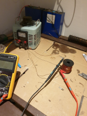
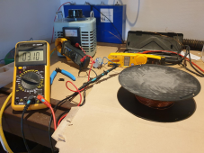
I tried hooking up a spool of 1mm enameld wire directly to the variac. (That is alot of winds running about 70 meters) At 4VAC the variac begins grouwling and I do not dare to take it any further.
1645550392041.png
Is this because the coil is saturated? and adding a core of some kind will increase it's 'range'?

It does seem that having many winds will reduce the likeliness that the circuit breaker will trip.
 
I tried hooking up a spool of 1mm enameld wire directly to the variac. (That is alot of winds running about 70 meters) At 4VAC the variac begins grouwling and I do not dare to take it any further.

Is this because the coil is saturated? and adding a core of some kind will increase it's 'range'?

It does seem that having many winds will reduce the likeliness that the circuit breaker will trip.

Yes, saturating and suddenly drawing high current, I think.
Using the step-down transformer you'll get to rotate Variac knob through a larger range to adjust voltage more precisely.
I did the same thing today, but added a 4 ohm resistor in series with the DUT. That way as it suddenly saturates and additional voltage only experiences the 0.040 ohm winding resistance, current increased more gradually. I got up to about 2A.

I'm told slope of BH curve is relative permeability. I think that is ratio of that slope to slope of air core. If you just have a piece of core inside the coil, I think that is composite relative permeability of magnetic path through core and through air to complete magnetic circuit.
With my added resistor I'm going to drive deep into saturation, see if it is just a straight line above that. Should get better Hc, Br, Bs values in those conditions.
 
I have some promising news which suggests that the powder is helping increase the voltage. it does not seem to do anything to the apms the coil is drawing.

Variac → isolation transformer (220 → 12) → +- 290 turns 1mm coil​
no iron core​
amp in variac​
amp in coil​
VAC in coil​
variac setting (V)​
0​
0.122​
<0.1​
0​
50​
0.114​
0.3​
0.53​
100​
0.13​
0.5​
1.02​
150​
0.16​
0.8​
1.48​
200​
0.172​
1​
1.82​
max​
0.195​
1.2​
2.21​
iron core (+-750g)​
amp in variac​
amp in coil​
VAC in coil​
variac setting (V)​
0​
0.102​
<0.1​
0​
50​
0.105​
0.3​
0.73​
100​
0.122​
0.5​
1.44​
150​
0.145​
0.8​
2.04​
200​
0.167​
1​
2.62​
max​
0.193​
1.2​
3.22​

1645627590475.png
 
I am going to try +- 630 turns (my original goal) now to see if that will not make the variac grouwl when I hook up the coil directly.
With the isolation transformer in between the variac and the coil the variac does not grouwl even when at the max setting.
 
also I do not believe my tesla meter can detect any magnetic field though. Or perhaps 50Hz is too fast and it averages out on the background field strength. If anyone has a suggestion on how to test that I am all ears.
 
Back
Top