diy solar

diy solar

[solved]WARNING. here be dragons. Stress testing a single cell with a DIY transformer

For strong enough field, you can use a pickup coil and read AC volts.
One guy at work has a hand-held meter he uses to check magnetic field around transformers.

At low AC voltage, coil around core is an inductor. V = L x di/dt, or V = I x j w L (where "w" is a stand-in for omega = 2 pi f)
That gives linear Irms / Vrms ratio.
Above saturation, response takes on the V = I x R, where R is winding resistance.
As you turn up Variac, current shoots up and is hard to control.

Put a resistor or light bulb in series with variac (or with step-down transformer). That will let you turn knob more smoothly and control current to what you want. Then record voltage and current (two or more significant digits) and graph. If clamp ammeter doesn't have good enough resolution, use 10 turns of wire to scale reading 10x.

I just used the resistor for that purpose at work. My choke was 0.040 ohms DC, an I used a 4.0 ohm power resistor.
 
For strong enough field, you can use a pickup coil and read AC volts.
sweet. excellent idea. thanks.

Put a resistor or light bulb in series with variac (or with step-down transformer). That will let you turn knob more smoothly and control current to what you want. Then record voltage and current (two or more significant digits) and graph. If clamp ammeter doesn't have good enough resolution, use 10 turns of wire to scale reading 10x.
yes will do once I am doing playing with physics. I mean this is sool cool those iron particles standing up ;)

1645633113581.png
 
Looks like high-speed photograph of an explosion.

1645634645394.png


My wife just got something like this; I haven't tried it yet. 30 to 300 Hz magnetic field detector (meant to measure ELF from appliances and power lines.)

 
update:

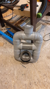
toroidal, how ever efficient, is not for me ;( it proves too unwieldy to wind coils.

I am going with @Hedges suggestion and use pvc pipes while prototyping.

3d printing a similar structure with ferromagnetic filament can come later should we need a performance boost.

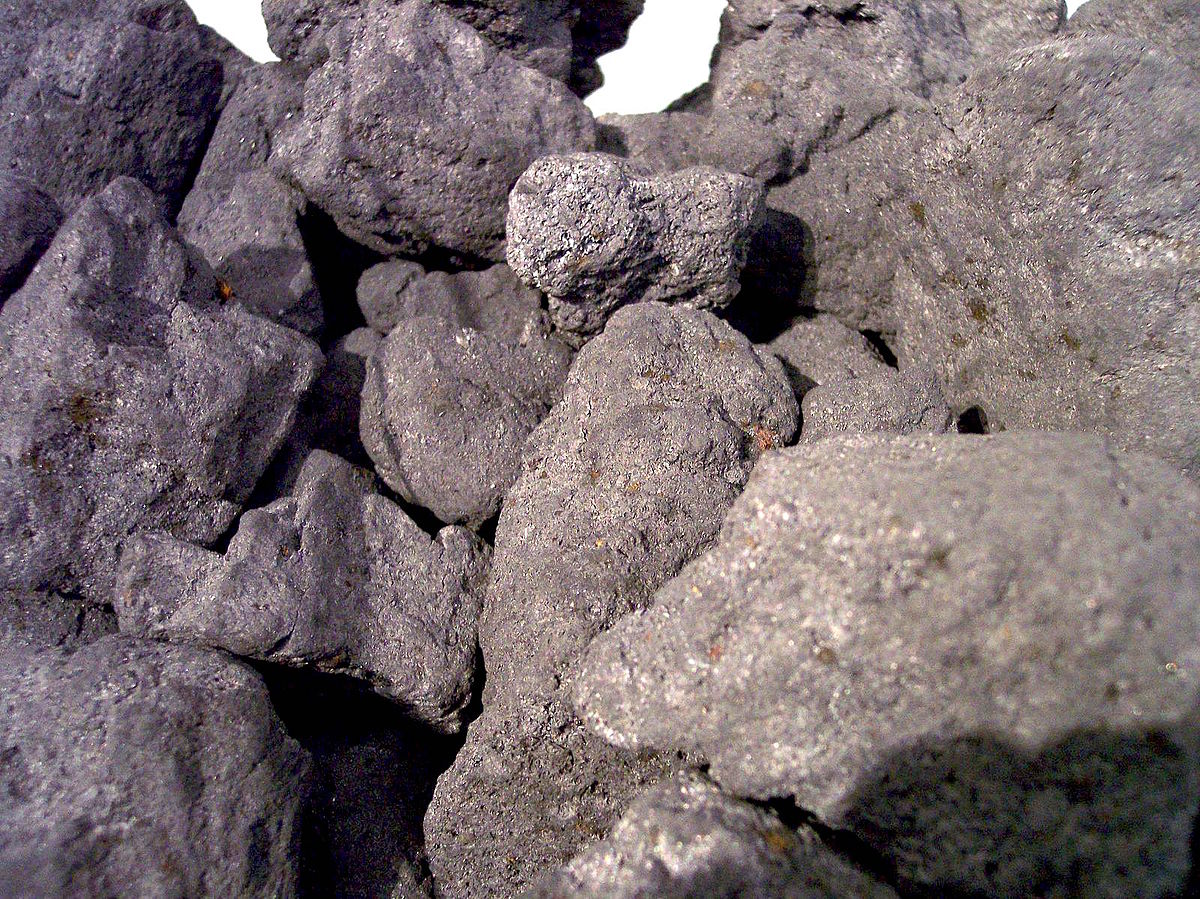
I am waiting for 25kg of iron powder to arrive

1647092421908.png
 
ahh in the background one can see a glimpse of the alternator magnets ;) still faar too wobly to use and test. waiting to my 3d printer adventure to come to fruition
 
let the carnage commence!

25kg iron powder arrived today and am now able to crank the variac up to 230VAC without reaching the 8 amps limit, imposed by the variac, in the primary coil.

1647448182651.png

I am now figuring out how many winds the secondary coil needs to produce 3.6VAC.

Currently getting 1.39 out of secondary
 
lol, while adding secondary winds the voltage does go up but also the amps drawn by the primary coils.

I really am not looking forward to do math and figure out the sweet spot so i'll also increase the primary coil and the core size to counteract this phenomenon
 
Primary amps go up when you add more turns to the (open circuit) secondary?
 
rather than increasing the primary winds and increasing the core size first I am going to try to make the core smaller in diameter (in fact increasing the primary coil winds but keeping the primary wire length the same) and longer. So that more of the primary coil winds are closer to the core. and then wind the secondary coil directly on top of the primary coil.
 
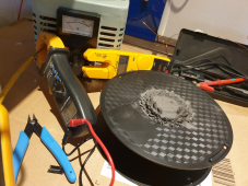
Also can someone please confirm if I tested the iron powder for conductivity correctly.

I used the setting that beeps when I touch the probes together or put them on something electrically conductive.

When I place the probes on the iron powder really close together it does not beep still showing OL as if the iron powder is not conductive.

If that is correct then I will upsize my first core attempt and make it hollow and fill it to the brim with this iron powder.


View attachment 84380

The variac has arrived in the meantime. still in the box so I'll show it off once it is unpacked and ready to rock
Are you gonna build a bridge? Fully erected-fied?
 
Maybe if you mix in some coke and apply RF to the coil, you can induction heat and smelt iron out of that powder.


yes, it baffles me. Granted it is most likely because I lack the perseverance to plow through the raw hard science first.

I am a more hands on kind of person.

I first simulated with a relatively ideal choke model (inductors with coupling coefficient and resistance from measurement), which looked perfect.
Measurements not as good at blocking common-mode, and varied between models.
I tried unsuccessfully to get measured hysteresis curves and Spice with "Chan" model. It looked something like an "S", but crossed over itself.
Second time was the charm, using mathematical integration not analog.
Now I'm playing with residual magnetization and demagnetization, but models still aren't replicating measurements perfectly (just the hysteresis curve.)
Next I'll try a magnetic field sensor. Using a core with a gap, but don't know yet how to see what field strength simulation says is in the gap.
 
I just had a brain
I first simulated with a relatively ideal choke model (inductors with coupling coefficient and resistance from measurement), which looked perfect.
Measurements not as good at blocking common-mode, and varied between models.
I tried unsuccessfully to get measured hysteresis curves and Spice with "Chan" model. It looked something like an "S", but crossed over itself.
Second time was the charm, using mathematical integration not analog.
Now I'm playing with residual magnetization and demagnetization, but models still aren't replicating measurements perfectly (just the hysteresis curve.)
Next I'll try a magnetic field sensor. Using a core with a gap, but don't know yet how to see what field strength simulation says is in the gap.
At least I understand it to some degree. 0.00000000000000000001% that is ;(
 
But I just had a brainwave.

What if I use a piece of pipe only and wind the primary and secondary coil on there. And then fully surround the coils in iron powder. so there is absolutely no space left that is not ferromagnetic.

is that worth a try or a sure recipe for nuclear plumes?
 
What if I use a piece of pipe only and wind the primary and secondary coil on there. And then fully surround the coils in iron powder. so there is absolutely no space left that is not ferromagnetic.

I think it is primarily inside the coils where magnetic field is formed. Contribution from wire wrapped around on all sides contributes.
Outside the coil, the wire is seen going left, then further away going right. Their contributions tend to cancel (but not entirely because at different distances.)
If current goes out in one wire of a twisted pair and returns in the other wire, field cancels almost perfectly because wires take turns being same distance from point of observation. "loop area" formed by two wires is small, just insulation thickness, and loop orientation periodically reverses so cancel each other.

Magnetic powder outside coil would make a "shielded" coil. That traps stray magnetic field so not as much is detected at a distance. Some chokes, transformers, and speakers for use with TV sets have magnetic shielding.

You plan to use coils with moving magnets for a wind generator, so you need an exposed portion of center of coil (or core through coil) for magnets to couple to.
Those magnets should not couple to magnetic powder or other core material that would steer the magnetic field outside coil of wire. You want all field going through the coil, not around.
 
I think it is primarily inside the coils where magnetic field is formed. Contribution from wire wrapped around on all sides contributes.
Outside the coil, the wire is seen going left, then further away going right. Their contributions tend to cancel (but not entirely because at different distances.)
If current goes out in one wire of a twisted pair and returns in the other wire, field cancels almost perfectly because wires take turns being same distance from point of observation. "loop area" formed by two wires is small, just insulation thickness, and loop orientation periodically reverses so cancel each other.

Magnetic powder outside coil would make a "shielded" coil. That traps stray magnetic field so not as much is detected at a distance. Some chokes, transformers, and speakers for use with TV sets have magnetic shielding.
Looks like you are correct ;) as it did not work. I could not get the variac all the way to 230VAC before the circuit breaker tripped. Even though amps on primary coil stayed below 8 amps I think it was because the amps going into the variac rose really fast.

1647705676115.png
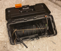
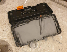
transformer in my toolbox without powder

but i've got more than 25kg of iron powder so better to use it
1647705755334.png


Like I said this did not work either and went ahead with tinkering.

And.. drumrolllsssssssss.

Success!!!!!

I think

1647705849006.png
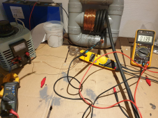
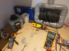
Here you can see that the variac in draws 8.26 amps while at full power (230VAC) and the primary coils only draws 1 amp.

The secondary coil produces 6.23 VAC.

Now before I remove the variac and hook up the transformer to the mains power directly (meaning the amps in the primary coil can go up to 16 amps before the circuit breaker trips)

How do I limit the output of the secondary coil to 140 amps? because I do not want to force feed my cell with like a 1000+ amps
 
Variac draws 8.26A at 230V? that's 2000VA
While driving only 1A? at what voltage?

If primary of your DIY transformer (secondary of variac) carried similar 8A, 230V, I would think it was acting as an inductor. 2000VA but near 0W
I don't understand 8A on Variac primary. Without load on secondary (real or imaginary), I expect little current flow in primary.

6.23Vrms on DIY transformer. You've got a nice "filament" supply there.
But what current can it drive? Reduce variac to minimum. Short out that "battery cable". Gradually increase variac without exceeding circuit/breaker capacity, see what current it can drive.

Using variac you should be able to adjust/limit output current and power.
Concern of course is exceeding voltage of cells. An analog circuit monitor cell voltage, and releasing coil of a NO relay on Variac primary, could be your single cell BMS.

For a CC/CV supply, how about a stepper motor turning down the Variac as voltage approaches target?
Or just disconnect this supply, switch to a regulated supply.

Filtering ripple voltage of 140A battery charger is left as an exercise for the reader.
 
Variac draws 8.26A at 230V?
yes
While driving only 1A? at what voltage?
yes.
I am assuming 230VAC. As the variac is maxed out and the analog display dangles around 230V.
Should I confirm this?

6.23Vrms on DIY transformer. You've got a nice "filament" supply there.
Can you please elaborate?

Using variac you should be able to adjust/limit output current and power.
Ok, i'll use the variac then to slowly increase the power to the battery cell while measuring voltage and amps going into the cell.

For a CC/CV supply, how about a stepper motor turning down the Variac as voltage approaches target?
hahahha ;) I am afraid I do not have time for an extra project ;(

Or just disconnect this supply, switch to a regulated supply.
Do you mean not use the current power socket to feed the variac but use a regulated power source?

Filtering ripple voltage of 140A battery charger is left as an exercise for the reader.
I'll read up on that to see if I will be worried about that
 
Back
Top