diy solar

diy solar

Solving for voltage drop over 200'

I think I agree about the spit phase approach ...after doing more research and finding real world prices.

A sungold 6kw split phase is 1199 right now. Where as two transformers will likely run me 1500. ...and add two more parts into the system.

I spoke to my contractor and he feels confident in our ability to run another set of conductors. Those would give us 2x 10awg solid copper. Or bigger
Good analysis.

I like the idea of bumping the voltage up to 480vac for transmission, but transformers are expensive, and 480v scares some people.
Split phase is worth a good look. Do you have 10-3 and a ground? I think you can drive a ground rod in at the cabin and create ground there with your 10-3.
Is a Sungold inverter a good name? Is it a listed component? Do you need any agency listing?
I agree - Propane appliances are popular with limited electricity. Your applances are killers.
Have you given any thought to a simple buck-boost transformer? Bump the voltage up by 10% and call it a day.
 
Before throwing money at it add the wire, as in your plan and parallel it with the old one and see if that helps with the dimming. I know you aren’t supposed to parallel less than 8 awg but we are taking about sea van and tent.
 
Before throwing money at it add the wire, as in your plan and parallel it with the old one and see if that helps with the dimming. I know you aren’t supposed to parallel less than 8 awg but we are taking about sea van and tent.
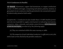
Whoever said you aren't supposed to parallel less than 8AWG?
 
Is the complaint just light dimming? YOu can probably find some LED lights that dont dim with reduced voltage. If they have a constant current source you probably wouldn't notice any dimming. What are the other issues?
 
Your post says 10/3 copper so you should have black white red and ground. That’ll give you 120/240 right now. If so you can get the new inverter and run a test on it. Voltage drop shouldn’t be as bad if you can separate it evenly. Others have posted the voltage drop numbers.
how many bends do you have in the 2” conduit? You might be able to pull in some 2/2/2/4 awg aluminum cheaper than 10awg copper and have a lot more capacity. Technically your not supposed to parallel conductors smaller than 1/0 but I’m not telling anyone ;)

I pulled 1/0-1/0-1/0-2 350‘ in 2” pvc recently So it’s doable.

please don’t drive a ground rod instead of an equipment grounding conductor. It’s dangerous and won’t trip the breaker if there’s a short to ground It’ll just sit there energized waiting to shock anybody that touches the metal frame of whatever is shorted out.
 
#10 wire is near 0.001ohm/ft. Your total is near 0.4 ohm. At 25A that is a 10v drop. Ok, yes, that is a good chunk of the 120v. I would think if you set inverter to 120vac then at max load you are at 110vac. Is this really a problem?
 
Interesting. Thanks for the research. I always thought that you could parallel but you had to protect with breaker for the smallest wire gauge. It only helps if you are dealing with voltage drops.
No problem. I think it’s because the conductors have to have exactly the same characteristics or else more current will flow over one conductor and overload it. The smaller the conductor the more chance of an overloaded conductor. Like you said sizing the breaker for the smallest conductor would alleviate that problem. I imagine the code panel thinks Installations can be messy enough and doubling up conductors is one more point of failure to worry about.
 
#10 wire is near 0.001ohm/ft. Your total is near 0.4 ohm. At 25A that is a 10v drop. Ok, yes, that is a good chunk of the 120v. I would think if you set inverter to 120vac then at max load you are at 110vac. Is this really a problem?

For resistance heating loads, just dims the lights.
Motor starting, surge about 5x running so might never start, just overheat and trip breaker.

This is why I prefer the drop in PV DC, rather than in AC. Even if 10V out of 120V, it is just 8% of power lost, no impact on AC voltage generated. Surge from batteries is unaffected, just PV production and only in good times.

Transformers are wound with about 5% extra turns on the primary. No-load, AC voltage is 5% high. At max rated current, winding resistance drops AC voltage to 5% low. Similar to the 10V drop out of 120V across his wire run.
 
So much good information. I just realized another fundamental mistake. ...this one made by the contractor.

He ran 10/2 not 10/3. I have black, white, ground
 
Another mistake is for runs of above 100 feet, you should go up one wire size per hundred feet. So the 10 ga wire probably should have been 6ga.

Here is another thought - look at some direct bury wire - both aluminum and copper.
 
So much good information. I just realized another fundamental mistake. ...this one made by the contractor.

He ran 10/2 not 10/3. I have black, white, ground

Here's a 3kVA transformer for $345 delivered.
Not perfectly clear details, but appears to have 120/240V secondary and 240/480V primary.


That could serve as a 120/240V auto-transformer. But primary wining might be limited to 1500W per 120V leg. There will be some voltage sag in driven leg (same number of turns in each.)

Two 120 in parallel, isolation to two 240V in parallel (using "primary" and "secondary" backwards) should deliver 240V over your "transmission line".
Probably running a bit low in voltage if used backwards, because secondary will have extra turns to make up for voltage drop from winding resistance.

A second transformer would convert back to 120V at far end, or give 120/240V split-phase.

With two transformers and 240V transmission, double voltage 1/4 the power loss.
Could also be used for 480V transmission, 1/16th the power loss. I might ground the center tap to ensure neither wire ever higher than 240Vrms from ground (well within 600V insulation rating of wire.)

All assuming it does in fact have 2x 240V primary windings, 2x 120V secondary.
 
Hey all, I need some advice on solving a voltage drop issue that has emerged due to some planning and provisioning mistakes which I made.

The layout...

oad was going to be no more than about 10a. I should have gone with a higher awg and 240 from the start. But, alas, I didn't.

The Inverter has been upgraded from 3kw to 5kw and the peak load now is about 25 amps over that 120v 200' run now that the cabin has a new induction cook top, electric kettle, fridge, and mrcool minisplit.

.

What would you do ?

Well as this is in the off-grid section, you are totally off grid ?

If so, my advice would be to diversify.

You appear to have all your egg's in one basket. What happens when your inverter dies ?

All heavy loads, where possible, should be on propane with a big storage tank (500-1000 gallon). Cooking, fridge, hot water, heating, even supplemental if you do wood burning or oil, or kerosene for heat. You will be glad for this when your power dies. Try and get dual electric/power units when possible.

Without checking, but on previous years experience, step up and step down transformers typically cost $300-$600 each (do your research).

Or invest in 200 feet of cable instead. Less to go wrong. Even 4/0 (really large, approx. 1/2 inch diameter) underground cable is around $700-$750 for 200 feet.

But all this depends on funds. Little by little unless you have plenty of disposable income.

YMMV.

ADD: You don't need to jump into a big propane tank, initially. You can use smaller ones, 25lb., 100lb ($168 at Home Depot). Whatever gets you started. More work, but less money.
 
Last edited:
Back
Top