Hi All,
I'm new to the forum, and solar power in general. I'm trying to pick things up, but if I say something below that doesn't quite make sense, please call it out. I may have more info to back it up, or I may just be wrong in my assumptions.
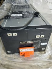
I recently acquired a pair of Sonnen/Sony/MuRata 2.1Kw LiFePO 48v battery units, and I'd like to make use of them without damaging them. They are designed to be part of a specific system, and are overseen by a battery management unit that I don't have. That said, they do appear to have an internal BMS which may allow me to use them without the external control and without purchasing new BMSes. Does anyone have experience with these batteries that they can share?
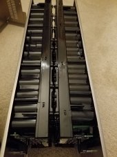
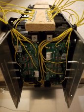
I took one of them apart and found two battery packs in each unit. The packs are 25.6v each and use US26650FT cells in a 8S14P layout. The cells are 3.2v, 3000 MaH according to MuRata, who I believe is their manufacturer. The ratings on the unit match the math for those cell values.
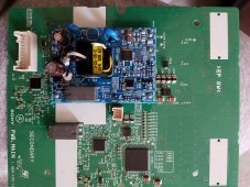
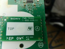
Behind the faceplate, there's the main terminal board with a shunt resistor and a small duplex wire which goes into the unit - I assume as current sense. There's a separate board with Renesas 16bit MCU (R5F21368MNFP) which handles the serial comms to other batteries and the battery management unit. I don't know if it's RS485, Modbus, or something proprietary. The MITSUMI IAM-A61 comm connector is an oddball and doesn't lead me anywhere.
That comm board connects to the main board via a 22 pin connector. The main board is populated with SONY branded chips that I can't find any details about. CXD5244R, CXD5243R, etc. The main board has a daughter board, and another small board with what appears to be an antenna. WiFi? Bluetooth? Seems odd to have an antenna buried so deep into the case.
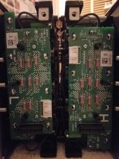
The main board then plugs into each battery module board using a 30pin connector each. There aren't any components that I can see on the backs of these battery pack boards, but they are tightly mounted and soldered to strips of metal coming out of the packs. It's possible some small smd components are hidden back there.
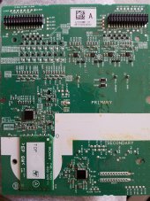
There are enough contact points on each board for the 8 stings of batteries in each pack. There's a connector with 4 wire pairs which go around the pack into blobs of white silicone. I assume these are temp sensors. There are eight 22ohm resistors and some small smd components on the boards. The wires feeding the + and - to these boards are thin, maybe 18 gauge or so. The battery pack's main terminals are connected directly to the cells.
Back on the main board, there are 16 transistors arraigned in 2 rows of 8. I think these control passive balancing of the cell strings through the resistors. The big question is if this is done internally, or if the external unit calls the shots. Given all the microchips on here, I'm thinking it's capable of handling the cells by itself. What do you think?
How would I go about testing to find out if the internal BMS is working on it's own?
I'm new to the forum, and solar power in general. I'm trying to pick things up, but if I say something below that doesn't quite make sense, please call it out. I may have more info to back it up, or I may just be wrong in my assumptions.
I recently acquired a pair of Sonnen/Sony/MuRata 2.1Kw LiFePO 48v battery units, and I'd like to make use of them without damaging them. They are designed to be part of a specific system, and are overseen by a battery management unit that I don't have. That said, they do appear to have an internal BMS which may allow me to use them without the external control and without purchasing new BMSes. Does anyone have experience with these batteries that they can share?
I took one of them apart and found two battery packs in each unit. The packs are 25.6v each and use US26650FT cells in a 8S14P layout. The cells are 3.2v, 3000 MaH according to MuRata, who I believe is their manufacturer. The ratings on the unit match the math for those cell values.
Behind the faceplate, there's the main terminal board with a shunt resistor and a small duplex wire which goes into the unit - I assume as current sense. There's a separate board with Renesas 16bit MCU (R5F21368MNFP) which handles the serial comms to other batteries and the battery management unit. I don't know if it's RS485, Modbus, or something proprietary. The MITSUMI IAM-A61 comm connector is an oddball and doesn't lead me anywhere.
That comm board connects to the main board via a 22 pin connector. The main board is populated with SONY branded chips that I can't find any details about. CXD5244R, CXD5243R, etc. The main board has a daughter board, and another small board with what appears to be an antenna. WiFi? Bluetooth? Seems odd to have an antenna buried so deep into the case.
The main board then plugs into each battery module board using a 30pin connector each. There aren't any components that I can see on the backs of these battery pack boards, but they are tightly mounted and soldered to strips of metal coming out of the packs. It's possible some small smd components are hidden back there.
There are enough contact points on each board for the 8 stings of batteries in each pack. There's a connector with 4 wire pairs which go around the pack into blobs of white silicone. I assume these are temp sensors. There are eight 22ohm resistors and some small smd components on the boards. The wires feeding the + and - to these boards are thin, maybe 18 gauge or so. The battery pack's main terminals are connected directly to the cells.
Back on the main board, there are 16 transistors arraigned in 2 rows of 8. I think these control passive balancing of the cell strings through the resistors. The big question is if this is done internally, or if the external unit calls the shots. Given all the microchips on here, I'm thinking it's capable of handling the cells by itself. What do you think?
How would I go about testing to find out if the internal BMS is working on it's own?