diy solar

diy solar

Spades too small for terminals - what to do?

jdege

New Member
Joined
Dec 16, 2020
Messages
138
I'm in the basement, working up an electric outboard, prior to installation on my boat.

Components:
  • Elco 9.9 electric outboard
  • Epoch 48V 100Ah LiFePO4 battery
  • Epoch 48V LiFePO4 charger
  • Victron BMV-712 battery monitor with shunt
The outboard came with pre-made cables for throttle and ignition key, and for power. The power cable has a connector on one end that matches the outboard on one end and side terminals on the other (and a fuse already wired into the positive). It also came with an extra 12-inch length of cable in the same gauge with the same sized spades.

The charger also included a cable with spade connectors.

The battery has screw terminals, and the spades on the cables fit these fine.

The problem is the Victron shunt. The screws on it are larger, and the spades won't fit.

So what should I do?
  • Drill out the spades so they fit?
  • Cut off the spades and crimp on new? Note - I don't have any crimpers that would serve.
  • Have a couple of short bits of cable with spades of the right size, and connect to the existing cables? Again, note - I have none of the appropriate materials or tools, and how would I connect them to the existing cables?
 
Do you have pictures of the spade and with the shunt pls

Really wants doing properly on a boat , don't want leaving stranded
 
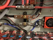
Any suggestions as to what screws to use, to connect the spades to the copper link?
 
The bus bars that you are showing AFAIK are not rated for 48 volts.
???

Conductors are rated for current, not voltage.

The 2/0 cable I'm using has a cross section of 67.4mm^2.

A 1/4×1 inch copper bar has a cross section of 161.3mm^2. More than even a 4/0 cable.
 
???

Conductors are rated for current, not voltage.

The 2/0 cable I'm using has a cross section of 67.4mm^2.

A 1/4×1 inch copper bar has a cross section of 161.3mm^2. More than even a 4/0 cable.
193 amps at .25 inch thickness and 1 in wide according to online calculator.
 
Last edited:
Max current for this application is 98A.
You should be fine with 1/8" X 1" copper bar. Just make sure when you drill your holes they are flat with no burrs on the edges.

And I should add, I put a plastic cover over my bus bars, and only took it off for the picture.
 
Depends on your future plans. I have been surprised at the number of times a good crimper has paid off. I have the Victron distributor and put on lugs to match. Just another perspective.
 
???

Conductors are rated for current, not voltage.

The 2/0 cable I'm using has a cross section of 67.4mm^2.

A 1/4×1 inch copper bar has a cross section of 161.3mm^2. More than even a 4/0 cable.

The conductor is amps but but your positive bus bar shown has an insulator base and I have never seen one like that rated for 48 volt use.
 
I wouldn't drill out the connector. You loose surface area. What I did for a rarely used device is cut the ring terminal on the side opposite the cable, and spread the sides a little until it fit over the terminal. Don't know the long-term implications. It won't fall off the terminal, but maybe nut is not as tight?
 
Do you have a fuse in circuit?

Many of the marine stores have facilities to make up custom cables.
 
I wouldn't drill out the connector. You loose surface area. What I did for a rarely used device is cut the ring terminal on the side opposite the cable, and spread the sides a little until it fit over the terminal. Don't know the long-term implications. It won't fall off the terminal, but maybe nut is not as tight?
I've done things like that for electronics projects, e.g. 200mA at 5V.

This is electric propulsion, 100A at 48V. There are a lot of shortcuts I might take at the minimal power levels involved in digital circuits that would terrify me, were I to try them at these power levels.

I included drilling out the connectors only for completeness. It wasn't actually on my list.

Do you have a fuse in circuit?

Many of the marine stores have facilities to make up custom cables.
Yes.

The main power cable to the outboard has a fuse wired into the positive side, and the charger has an internal fuse on the AC side.
 
The conductor is amps but but your positive bus bar shown has an insulator base and I have never seen one like that rated for 48 volt use.
We are talking about the shunt ... so, negative side only. (and if you are looking at the photo of my system, we aren't talking about positive bus bars so that doesn't apply here, but my system is 24 volts.)
 
Last edited:
I had a similar issue with my shunt. I had an MRBF fuse and holder which served as an adapter and also added a needed fuse.
 
Back
Top