diy solar

diy solar

Specific grounding diagram

JonL

New Member
Joined
Sep 18, 2020
Messages
291
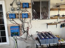
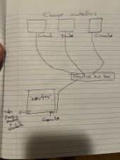
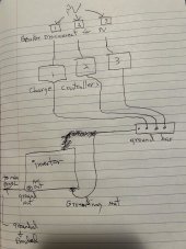
I’m presenting a diagram drawn out from PV to breaker disconnect to charge controllers to ground bar to inverter. The inverter goes to the main panel and is grounded and bonded. All equipment is victron.
I’m just asking one simple question is this right or is it wrong? Does the grounding look right? Thanks! ?
PS: this is for a house, not an off grid place or a van.
 

Attachments

  • AF2D4D66-8082-4702-BD01-7AB5574B879A.jpeg
    AF2D4D66-8082-4702-BD01-7AB5574B879A.jpeg
    146.6 KB · Views: 30
Last edited:
If the neutral is already tied to earth elsewhere there no need to have it done again at the invertor.
 
But if all wires shown are ground (not Neutral, which would be bonded to ground at main panel), then it looks good.
The grounds don't necessarily have to daisy-chain through inverter and SCC, could all form a star off a ground bar.
The enclosures of those components and boxes are NOT to be used as part of the conductor for a daisy-chain. i.e. two wires going to two different grounding nuts is not correct (as I understand.) There would need to be a wire inside the inverter joining those two screws, not just enclosure connecting them.
All connections have to be through wires and busbars, not metal enclosures. Some PV rack hardware is listed for use as grounding conductor.
(perhaps an exception for some listed equipment with ground connections? I noticed one of my inverters has ground terminals on DIN rail for PV, and separate ground connections in another compartment for AC connections, only cast metal enclosure providing connection between them.)
 
If the neutral is already tied to earth elsewhere there no need to have it done again at the invertor.
I thought the ground coming from the ground bar to the inverter was to complete the circuit, otherwise the charge controllers go to nothing but a ground bar and nothing else?
 
But if all wires shown are ground (not Neutral, which would be bonded to ground at main panel), then it looks good.
The grounds don't necessarily have to daisy-chain through inverter and SCC, could all form a star off a ground bar.
The enclosures of those components and boxes are NOT to be used as part of the conductor for a daisy-chain. i.e. two wires going to two different grounding nuts is not correct (as I understand.) There would need to be a wire inside the inverter joining those two screws, not just enclosure connecting them.
All connections have to be through wires and busbars, not metal enclosures. Some PV rack hardware is listed for use as grounding conductor.
(perhaps an exception for some listed equipment with ground connections? I noticed one of my inverters has ground terminals on DIN rail for PV, and separate ground connections in another compartment for AC connections, only cast metal enclosure providing connection between them.)
So are you saying that all my charge controllers need to be connected to my negative busbar and then do not tie anything to the inverter? This inverter is connected to the house panel.
Or should I just take the last connection to the negative bus bar instead of the inverter?
 
Last edited:
There’s no hook up to the batteries yet because I had to re-order the battery switch, because last time I hooked it up like this the switch fried!
 

Attachments

  • 86DD1AB7-EB1B-46F6-B844-3C932ED9261C.jpeg
    86DD1AB7-EB1B-46F6-B844-3C932ED9261C.jpeg
    355.1 KB · Views: 17
So is this one better connection? All grounds connected to the negative bus bar. Thanks
 

Attachments

  • 46422B75-C665-4C58-91A6-522842EBBAB4.jpeg
    46422B75-C665-4C58-91A6-522842EBBAB4.jpeg
    129.8 KB · Views: 9
No, don't connect ground/chassis to "Negative bus bar".
You can connect all ground/chassis to a "ground bar".

Do not connect PV+ or PV- to ground.
Possibly battery negative should connect to ground, depending on inverter manual and applicable electrical codes.

Neutral of AC ties to ground somewhere. Probably by your utility meter.

Mobile inverters pass through neutral from shore power pedestal (neutral should be grounded out there somewhere), and when disconnected from shore power they bond neutral to ground locally.
I heard that lithium batteries should not be grounded. I can ground the charge controllers to a separate ground bar that goes to a 6 foot ground at earth, but if there’s lightning doesn’t that create a loop?
 
This is the diagram I had originally, and it worked! The only thing I’m worried about is if I ground the charge controllers to a ground rod outside, will this create a loop? According to Will Prowse, you do not want to have a loop or it could fry all your equipment. As far as the inverter goes, I just left it without a ground to the chassis.
 

Attachments

  • 4D1DAE49-07FF-4ECD-B755-8A41FEE40378.jpeg
    4D1DAE49-07FF-4ECD-B755-8A41FEE40378.jpeg
    133.8 KB · Views: 7

At least not PV array negative bus bar.

Possibly battery negative should connect to ground, depending on inverter manual and applicable electrical codes.

Be very deliberate about connecting any current-carrying electrical conductors to ground network. Typically that is done in just one place. Sometimes none. RTFM.
 
At least not PV array negative bus bar.
Its my understanding that many of the solar charge controllers we use are non-isolating.
Which means that scc.pv.negative and scc.bat.negative are bonded internally.
Which means that if the dc core negative busbar is referenced to the dirt so is pv negative.

I've been thinking for a while that we should be using a single pole single throw disconnect on pv positive because pv negative is in fact grounded.
 
There was a time when code forbid disconnecting grounded negative wire. And yet, a lot of the equipment had a 1A fuse tying negative to ground as GFCI. The code has changed.

I prefer a 2-pole disconnect, so I know PV voltage isn't anywhere in the equipment I'm working on. If PV+ shorted to ground, and you somewhere disconnected negative conductor from ground, it would suddenly become high voltage. That could extend to battery terminals.

If I'm going to work on PV side of disconnect, I unplug the touch-safe MC connectors (after verifying no current flow, by measuring Voc for open circuit.)
At this point, I think I need to hire an expert to solve a few issues with my system. Does anybody know how to go about this, trying to find somebody is not easy, as there’s hardly anybody who knows this stuff! ?
 
AC wiring and ground should be well understood by an Electrical PE and city/county permit office. Electricians and contractors, maybe.
If related to inverter & charge controller the manufacturer or a good retailer (the kind who design systems.)

Here, we are a motley crew, but engineers, contractors, installers are among the lurkers. Some are well versed in NEC.

What issues?

What city and state?
I’d rather not go through any permit office. My system is not grid tied.
I live in Renton Washington
Number one problem, for some reason I keep getting a low battery light on my inverter. I have another post describing this horror show!
I’ve tried just about everything I can think of.
Number two problem, getting the right grounding so nothing like this ever happens again!
I’m definitely over my head!
Have you established that your symptoms are caused by a grounding problem?
 
Have you established that your symptoms are caused by a grounding problem?
No! One electrician I talked to said he couldn’t think of anything else that I haven’t tried already. He mentioned to check conductivity of each wire. I’m not sure how to do that, that’s why I am on YouTube trying to figure that out.
 
Back
Top