diy solar

diy solar

Split Phase, Single Phase, Parallel for LV6548

West Coast Canuck

New Member
Joined
Dec 15, 2020
Messages
36
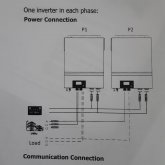
I have 2- mpp Solar Lv6548 wired up in what I think is called Split Phase and think that it is 180 degrees.
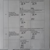
This is a first build and learning from everyone on this site has been great but being new to solar I am not picking up on all the terms so if anybody can help me with what I have wired to my A/C I would appreciate it. The first diagram is how I have the two inverters wired. the second diagram is from the Manual,Whitch do I choose. Thanks
 

Attachments

  • LV6548 split phase manual-20201020.pdf
    7.5 MB · Views: 82
  • WatchPower user manual.pdf
    1.9 MB · Views: 23
Ok I am just trying to understand if what i have wired from my 60 amp two pole breaker from the grid is referred to as split Phase(see attached as wired). The LV6548 refers it as One inverter in each Phase, but the Manual page (single page attached) asked for Split 120 or 180 phase diff
 

Attachments

  • Split Phase 2.jpg
    Split Phase 2.jpg
    44.9 KB · Views: 45
  • Split Phase.jpg
    Split Phase.jpg
    63.5 KB · Views: 42
First.... From your handle I assume you are in Canada....Is that correct? (Canada uses the 240 Split phase feed to the home)

The standard feed to the home in North America is from a 240V transformer with a center tap for neutral. This creates two 120V circuits that are 180deg out of phase with each other or a single 240 V phase. Therefor , Program 28, one of the inverters should be set to 2P1 and the other set to 2P2 with 180deg)

Note: The manual talks about Split phase that is 120deg out of phase but I have never heard of that before..... I can't think of a situation where that would be appropriate.
 
I am in Canada. Thank you for taking an interest to help me understand this issue, the help I have been given on this form has been un Parallel (no pun intended) thanks again
 
BTW: Make sure the communications cables are set up between the two inverters.
 
The standard feed to the home in North America is from a 240V transformer with a center tap for neutral. This creates two 120V circuits that are 180deg out of phase with each other or a single 240 V phase. Therefor , Program 28, one of the inverters should be set to 2P1 and the other set to 2P2 with 180deg)
Does this depend on the region or just local history in the US? My block appears to have a shared "small trashcan sized" transformer high on a pole feeding 3 wires. I thought each house taps into two of them and therefore any two phases are 120 degrees out of phase. I'll walk down the block and take a closer look tomorrow.

Or, are you saying there is another transformer inside each house's meter which converts these two phases into two 180-degree phases? I had assumed we were just assigned 2 of the 3 (120-degree separated) phases, and they alternate which phases each house receives to approximately balance the load on the 3 phases.

EDIT:
Or, are the 3 lines on the pole carrying two 180-degree phases and the third one is a neutral common to all houses? I guess that's what it is, now that I think about it, and everyone on the block uses the same 2 phases whereas another block over (with its own transformer) may use 2 other phases of the higher voltage 3-phase distribution. That would mean the service connection is 3 wires to each house and not 2 ... I need to look out the window to check when it's not dark.
 
Last edited by a moderator:
Does this depend on the region or just local history in the US? My block appears to have a shared "small trashcan sized" transformer high on a pole feeding 3 wires. I thought each house taps into two of them and therefore any two phases are 120 degrees out of phase. I'll walk down the block and take a closer look tomorrow.

Or, are you saying there is another transformer inside each house's meter which converts these two phases into two 180-degree phases? I had assumed we were just assigned 2 of the 3 (120-degree separated) phases, and they alternate which phases each house receives to approximately balance the load on the 3 phases.

EDIT:
Or, are the 3 lines on the pole carrying two 180-degree phases and the third one is a neutral common to all houses? I guess that's what it is, now that I think about it, and everyone on the block uses the same 2 phases whereas another block over (with its own transformer) may use 2 other phases of the higher voltage 3-phase distribution. That would mean the service connection is 3 wires to each house and not 2 ... I need to look out the window to check when it's not dark.
Yes, in North America the 3 wires going to each house is typically (Always?) two hots and a neutral

1616605803226.png
Yes, More than one house will often share the same transformer.

To tell the truth, I am not well versed on the different techniques used to balance the home loads across the 3 phases that is used in the overall grid distribution. However, I do know that in the last leg of distribution going to the poles behind houses, it is often a single phase .... not a 3 phase distribution. That single phase might have a few transformers on it for creating the split phase going to the house(s). The utility probably sends the different phases from a 3 phase transformer to different areas in the neighborhood.
 
Note: The manual talks about Split phase that is 120deg out of phase but I have never heard of that before..... I can't think of a situation where that would be appropriate.
I did a very quick search for 120deg split phase and did not find anything. The only thing I can think of is it is trying to allow the set-up for two legs of a 208 V 'delta' 3 phase.

With 208V 3 phase Delta there are 3 hot wires and a neutral giving you three 120V circuits and/or three 208V circuits
  • Between any single hot and neutral it is 120V. Each of the three 120V phases are 120deg out of phase with the other two.
  • Between any two hots is 208V single phase. Each of the three 208V phases are 120deg of of phase with the other two
Like I said, what is described in the manual would only provide Two hots and neutral. This would give you one 208V circuit and/or two 120V circuits that are 120deg out of phase with each other. I guess if you were trying to back up part of a system that is running 208V delta this configuration could be usefull..... but that is going to be pretty unusual, particularly for us DIYrs.
 
Yeah I checked and it looks like 3 wires are provided from the overhead service, with one wrapped with white tape indicating neutral. But actually I noticed my neutral wire does not appear to be connected! It's hard to tell without getting close to anything dangerous. Calling the utility company to come take a look.
 
Yeah I checked and it looks like 3 wires are provided from the overhead service, with one wrapped with white tape indicating neutral. But actually I noticed my neutral wire does not appear to be connected! It's hard to tell without getting close to anything dangerous. Calling the utility company to come take a look.
If the neutral to the house is disconnected, You would not get 120V....
 
If the neutral to the house is disconnected, You would not get 120V....
Yeah, and we do have working service. This makes me think my panel/meter/box has its own transformer, so it uses only the 2 phases from the utility company to drive the primary of that transformer; the utility's neutral is unused, and the house's neutral connected to the secondary of that hypothetical transformer goes to the ground rod in my foundation.
 
Last edited by a moderator:
I would be very surprised if that were the case.
You're right; false alarm. I was tracing the wires incorrectly as I looked out my window.

There are actually only 2 insulated wires from the pole providing the 2 hot voltages, and they're wrapped around a bare braided cable for support. The bare braided cable is connected at both ends using insulated ceramic couplers (two interlocking "U" type). But, then the braided cable is also bonded to the neutral on my side and to some other wire on the pole, so the utility is using that to provide neutral as well as structural support for the hot wires. Seems all is normal (except some fraying/UV damaged insulation that I should get fixed).
 
I have my LV6548's in split phase operation (US) I am using a 60a 2p breaker from my main panel to feed them. The only worry I have is with the shared neutral. Each inverter can output 54a so there is a potential to draw 108a total. Not likely that the unbalanced load (neutral) will ever see that, but in theory it is possible. Breakers are common trip so if either leg draws over 60 amps the 2 pole should trip. I still am running tests on my system, I but don't like the fact that the neutral is shared between the inverters without being able to accept wire sizing for 100a or a double neutral.

Just my thoughts
 
You're right; false alarm. I was tracing the wires incorrectly as I looked out my window.

There are actually only 2 insulated wires from the pole providing the 2 hot voltages, and they're wrapped around a bare braided cable for support. The bare braided cable is connected at both ends using insulated ceramic couplers (two interlocking "U" type). But, then the braided cable is also bonded to the neutral on my side and to some other wire on the pole, so the utility is using that to provide neutral as well as structural support for the hot wires. Seems all is normal (except some fraying/UV damaged insulation that I should get fixed).
Pictures..?
 
Pictures..?
My post was about me being wrong because I made a mistake following the various wires, and clarifying the actual connection to my utility company. I could go up there and take a picture but what exactly do you want to know? Do you you have some doubts about your own utility connection?
 
Back
Top