Hi, I'll try to make this brief, but please do ask if you need more details.
I'm building a portable battery pack that I can take camping and/or provide emergency backup power to a select few circuits in my house in a grid outage.
I designed everything on paper first and did all my load calculations and wiring diagrams before starting, but I've ran into an issue with wiring the cells. I'm at the point where I don't know if I should redesign everything to get around the issue, or settle for a tedious solution. I'm already $3K into the build and have purchased nearly everything, so redesigning at this point would be quite expensive. However, safety is my number one priority and I will do whatever it takes to build a safe and reliable battery.
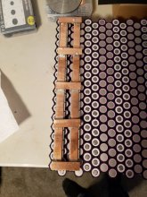
The battery will be composed of a total of 504 brand new Samsung INR18650-35E cells in a 36P 14S configuration using honeycomb cell holders. My goal is to be able to put out up to 30A at 120V, and I've calculated that this would be a C-rate of 0.69 on each individual cell. I also want to retain the ability to increase the inverter size in the future to upgrade the battery output, so I am over-engineering the wiring to handle loads up to 70A @ 120V which, on the DC side of things, would present about a 200A load to the battery. I have chosen to use properly sized copper bus bars to handle the cell connections and 18 AWG wire to connect each cell to the bus bar. Here is a photo of my bus bar assembly on one string of cells. I made 14 of these bus bar assemblies that will sit on top of every string of cells in the pack, but only one is shown in the picture below:

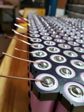
I am soldering a short piece of wire to each cell (using the correct technique with a high power soldering gun to get in and out as quick as possible).

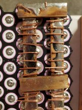
I then place the copper bus bar assembly so that I can fold the wires over it, in hopes of soldering them to the bus bar:

(The wires will be trimmed to length and the entire bus bar assembly will be Kapton taped off and/or or covered with a 3D printed ABS cover - this is just a test fit).
Now, the issue is, I cannot, for the life of me, get solder to melt on the copper bus bars using my Weller 240W gun. They just soak up too much heat. The photo above shows the bar tinned with a bead of solder which is one strategy I tried to get this to work. I built the bus bar assemblies with a torch and also tinned the bars with a torch, but obviously I can't use that on the battery itself.
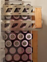
The other idea is to drill and tap holes in the bus bars to attach the wires, either directly with a screw, or with a second, thinner piece of copper bar that I can use as a clamp to sandwich the wires between. I'm not fond of either of these ideas because I'm worried something will loosen up over time as the pack heats/cools.
I really don't know how else to move forward. I am open to all feedback and ideas. Please let me know your thoughts!
I'm building a portable battery pack that I can take camping and/or provide emergency backup power to a select few circuits in my house in a grid outage.
I designed everything on paper first and did all my load calculations and wiring diagrams before starting, but I've ran into an issue with wiring the cells. I'm at the point where I don't know if I should redesign everything to get around the issue, or settle for a tedious solution. I'm already $3K into the build and have purchased nearly everything, so redesigning at this point would be quite expensive. However, safety is my number one priority and I will do whatever it takes to build a safe and reliable battery.
The battery will be composed of a total of 504 brand new Samsung INR18650-35E cells in a 36P 14S configuration using honeycomb cell holders. My goal is to be able to put out up to 30A at 120V, and I've calculated that this would be a C-rate of 0.69 on each individual cell. I also want to retain the ability to increase the inverter size in the future to upgrade the battery output, so I am over-engineering the wiring to handle loads up to 70A @ 120V which, on the DC side of things, would present about a 200A load to the battery. I have chosen to use properly sized copper bus bars to handle the cell connections and 18 AWG wire to connect each cell to the bus bar. Here is a photo of my bus bar assembly on one string of cells. I made 14 of these bus bar assemblies that will sit on top of every string of cells in the pack, but only one is shown in the picture below:

I am soldering a short piece of wire to each cell (using the correct technique with a high power soldering gun to get in and out as quick as possible).

I then place the copper bus bar assembly so that I can fold the wires over it, in hopes of soldering them to the bus bar:

(The wires will be trimmed to length and the entire bus bar assembly will be Kapton taped off and/or or covered with a 3D printed ABS cover - this is just a test fit).
Now, the issue is, I cannot, for the life of me, get solder to melt on the copper bus bars using my Weller 240W gun. They just soak up too much heat. The photo above shows the bar tinned with a bead of solder which is one strategy I tried to get this to work. I built the bus bar assemblies with a torch and also tinned the bars with a torch, but obviously I can't use that on the battery itself.
The other idea is to drill and tap holes in the bus bars to attach the wires, either directly with a screw, or with a second, thinner piece of copper bar that I can use as a clamp to sandwich the wires between. I'm not fond of either of these ideas because I'm worried something will loosen up over time as the pack heats/cools.
I really don't know how else to move forward. I am open to all feedback and ideas. Please let me know your thoughts!


