Hello, Wiring a subpanel in my RV, 110 volt single phase, subpanel powered by the "output" of a 2000watt inverter(with transfer switch built in). Moved 3 breakers from main panel to a subpanel, which powers the 110 volt AC plugs in the RV. Standard wiring: 3 Neutral white wires to isolated(floating) neutral bar,3 green to ground bar connect to metal subpanel housing, and black hot to breakers. Then I used a 10GA green wire to connect the ground bar of the subpanel to the ground bar of the main panel. Using a 10GA white wire I connected the floating neutral of the subpanel to the floating neutral of the main panel. I talk with two different inverter tech-supports persons, who told me to disconnect the neutrals form the subpanel to the main panel are it would cause damage to the inverter. Can anyone tell me why the neutrals should not be connected? I know there should be only one neutral to ground bonding which only happen when you plug into 110 volts shore power.


You are using an out of date browser. It may not display this or other websites correctly.
You should upgrade or use an alternative browser.
You should upgrade or use an alternative browser.
Subpanel powered by inverter neutral wire?
- Thread starter ChasRob
- Start date
Hedges
I See Electromagnetic Fields!
- Joined
- Mar 28, 2020
- Messages
- 20,535
A schematic would help to understand this.
Since it is an inverter with transfer switch, neutral is probably coming from main panel to the inverter.
The inverter may provide neutral/ground bonding when disconnected from shore power. I can imagine this causing some issue if both neutral and ground wired to main panel, but not entirely clear it would be a problem.
Some inverters have hot/neutral outputs which aren't 120V/0V (or floating), but rather +60V/-60V. I wouldn't have expected that with transfer switch included, but it is possible.
Since this is an RV not a house, I doubt any existing wiring had Romex 3 + ground where red and black went to two separate circuits but white neutral is shared. Where such wiring is used I would see a problem with pulling one of the hots (e.g. black) to the sub panel; it could get AC from inverter out of phase with AC from grid on the other hot (e.g. red) wire.
Thanks for your reply, The 110volts outlet plugs wired to the subpanel will work off gird via inverter,110 volt AC, and when plugged into the shore power or generator the Transfer switch allows the 110volts to the outlet plugs by bypassing the inverter, but still have 110volts to the plug. Can you elaborate on what you mean by not be in phase with each other?

If some things will be powered by the inverter, and other things will be powered by grid/generator, then the neutrals can't be tied because those sources will not be in phase with each other.
Hello, Wiring a subpanel in my RV, 110 volt single phase, subpanel powered by the "output" of a 2000watt inverter(with transfer switch built in). Moved 3 breakers from main panel to a subpanel, which powers the 110 volt AC plugs in the RV. Standard wiring: 3 Neutral white wires to isolated(floating) neutral bar,3 green to ground bar connect to metal subpanel housing, and black hot to breakers. Then I used a 10GA green wire to connect the ground bar of the subpanel to the ground bar of the main panel. Using a 10GA white wire I connected the floating neutral of the subpanel to the floating neutral of the main panel. I talk with two different inverter tech-supports persons, who told me to disconnect the neutrals form the subpanel to the main panel are it would cause damage to the inverter. Can anyone tell me why the neutrals should not be connected? I know there should be only one neutral to ground bonding which only happen when you plug into 110 volts shore power.
Here is a diagram of what I am talking about.Thanks for your reply, The 110volts outlet plugs wired to the subpanel will work off gird via inverter,110 volt AC, and when plugged into the shore power or generator the Transfer switch allows the 110volts to the outlet plugs by bypassing the inverter, but still have 110volts to the plug. Can you elaborate on what you mean by not be in phase with each other?
View attachment 32475
Hedges
I See Electromagnetic Fields!
- Joined
- Mar 28, 2020
- Messages
- 20,535
Since the inverter has neutral in and out (also hot and ground), should be fine to have sub panel only get neutral through the inverter.
Not clear what problem occurs if sub panel also has neutral wired directly to main panel, but no apparent benefit so especially if vendor said not to connect, then just leave isolated.
I see you have black wire for four loads going to breakers in sub panel, and corresponding white wires going to sub panel, which is good.
When inverter is running its AC output is probably asynchronous with grid, so each makes a sine wave that sometimes line up with each other (in phase), other times not (out of phase.) There are some situations (house wiring with one red and one black wire sharing a single white neutral) where I would expect the neutral to end up carrying twice the current it was rated for. Otherwise, I can't think of how tying all neutrals together causes harm.
Some inverters (Victron) appear to have all-pole disconnect, so when grid input goes away they isolate both hot and neutral wires of output from input. They then connect neutral to ground. Not sure if your inverter does that.
Cheap 4-life
My body is 2.63 trillion volts, .07v per cell
So if the inverter was powering a subpanel (in my house) with a manual transfer switch and indeed supplies 60v-60v to ground. should I make sure the inverters case is grounded to a separate (not the mains grid ac ground rod) ground rod so that 60v from inverter isn’t present on the grids ground. And so that the inverters ground isn’t connected to the ground bonded neutral?
Hedges
I See Electromagnetic Fields!
- Joined
- Mar 28, 2020
- Messages
- 20,535
I'm not sure I can recommend any way of wiring a +/-60VAC (center grounded) inverter into house wiring.
Hooked that way and giving it an isolated neutral, it makes neutral wire of a 110V outlet, including GFCI outlet, hot.
If tied to existing neutral (which is bonded to ground), it may put 60V between your new ground rod and house ground (unless case isolated).
If case is isolated, you'll have that grounded, but one battery terminal will be at 60VAC, and other battery terminal will be at 60VAC + Vbat.
With a suitable transformer it could make 120V (isolated) which could then have one end connected to a neutral that is bonded to ground.
Cheap 4-life
My body is 2.63 trillion volts, .07v per cell
The inverter and grid would supply a critical loads subpanel. The transfer switch would be a 3 pole switch. That’s one pole for each wire. Ground,neutral and hot from grid wired to each pole one side of the switch. Ground neutral and hot from inverter wired the same way to each pole of the other switch. This would completely isolate the grid from the inverter. So 60v couldn’t be on the grids neutral. But the subpanel and the critical loads still need an actual ground when the transfer switch is turned to inverter. So I suppose I need to install a ground rod just for the inverter?
Why would the battery have 60vac on it?
Why would the battery have 60vac on it?
Hedges
I See Electromagnetic Fields!
- Joined
- Mar 28, 2020
- Messages
- 20,535
These inverters are apparently non-isolated, generating perhaps +/-85VDC from battery, then 120Vrms AC (170V peak) from that.
I think the AC hot and neutral wires swing between +60Vrms and -60Vrms relative to battery. If you ground the "neutral", then "hot is 120VAC relative to neutral and I think battery negative is 60VAC.
If you isolated all of it from your house wiring, then grounded the inverter chassis (either to its own ground rod, or to ground wire of the house), it would put out that +/-60VAC, or 120 VAC between the two wires. That could run a regular 120V appliance. It's just that "neutral" won't be neutral. I would use it only with a cord, not feeding house wiring, and not for anything in a wet location.
Cheap 4-life
My body is 2.63 trillion volts, .07v per cell
Would it be ok to use the grids ground rod for the inverters ground?
You said not feeding house wiring. The inverter would only be feeding a few small critical loads that would be completely isolated (by the manual transfer switch) from the grids neutral, hot and possibly isolated from ground by a separate ground rod if needed. So essentially turning the house wires for the critical loads outlets into a cord that isn’t connected to the grid at all when switch is turned to inverter
You said not feeding house wiring. The inverter would only be feeding a few small critical loads that would be completely isolated (by the manual transfer switch) from the grids neutral, hot and possibly isolated from ground by a separate ground rod if needed. So essentially turning the house wires for the critical loads outlets into a cord that isn’t connected to the grid at all when switch is turned to inverter
Hedges
I See Electromagnetic Fields!
- Joined
- Mar 28, 2020
- Messages
- 20,535
I wouldn't have a problem using house ground wire and ground rod, for instance make a 3-prong cheater cord, tape off hot and neutral, just use the green wire to ground it. When I have an ESD mat or similar with ring terminal on ground wire I put that under screw at electric outlet cover plate (or electrical box screw, since usually grounded metal where I worked.)
I have well-behaved inverters feeding my house wiring. They are powerful enough to drive A/C and anything else on the property. It is just my battery capacity that is limited.
A +/-60V inverter (center grounded) may not be large enough to power many loads. Or is it "modified sine wave", not good for motors like refrigerator? I would use that direct wired, like a separate extension cord not tapped into house wiring. I wouldn't switch neutral (or ground) in house wiring. If it is pure sine wave and the only problem is non-isolated, then I'd put it through a transformer. That would produce 120V or 120/240V split phase, which could feed the house. In that case, maybe use a cord to hook it up to a generator switch (which could also be used with a gasoline generator if desired.)
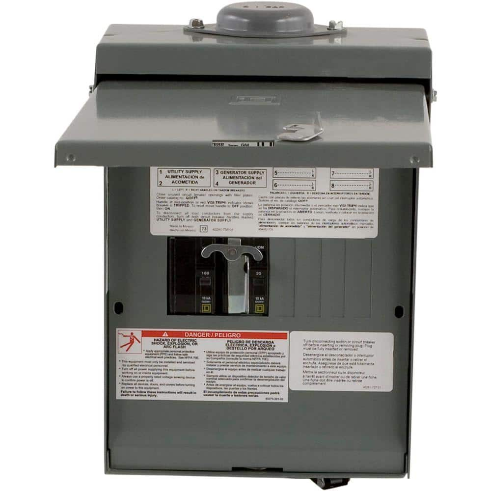
Square D QO 30-Amp 4-Space 8-Circuit Generator Main Breaker Outdoor Manual Transfer Switch QO1DM10030TRBR - The Home Depot
The Square D by Schneider Electric QO 30/100 Amp 4-Space 8-Circuit Temporary Transfer Generator Panel helps you change from utility power to a standby source with the flip of 2 QO main circuit breakers.
www.homedepot.com
Similar threads
- Replies
- 5
- Views
- 292
- Replies
- 2
- Views
- 264
- Replies
- 0
- Views
- 184
- Replies
- 2
- Views
- 166