doggy
New Member
- Joined
- Dec 11, 2021
- Messages
- 26
I have installed 8 EVE 280AH LFPs in 2p4s with a 200A (max 300A) JK BMS.
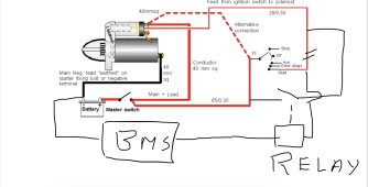
All is good. However, the starter motor is around 1400W or 120A but presumably draws a lot more on start up (cranking a 3cyl diesel on my boat). It is presumably going over 300A because the BMS is triggering a SCP (Short Circuit Protection) disconnect. The interval in the settings is 1,500uSecs or 1.5msecs. I'm reluctant to increase it much and it would probably need to be about one second for the starter motor to start moving and drop the current.
So I'm looking for suggestions on how to handle this. I'm not interested in swapping out the BMS for a relay one because I've done a lot of work to interface 2 MPPT solar controllers, engine alternator regulator and a boost charger to the BMS for another battery bank. Short term I have an AGM in parallel but I'm not going to keep things that way. I'm sure others will have had this issue. My couple of thoughts are:
1. A solenoid bridging B- and P- on the BMS triggered in parallel with the starter solenoid or
2. A bunch of Super capacitors in parallel with the BMS output to sop up the stalled initial starter current.
Thanks,
Dave