diy solar

diy solar

Sunny island 6048

Protected loads panel with Sunny Boys. Do you have a load-shed relay for other loads?
No I don't.... is that something to dump power into like a water heater element if battery is full or something to disconnect power to loads before inverter quits due to low battery?
 
No I don't.... is that something to dump power into like a water heater element if battery is full or something to disconnect power to loads before inverter quits due to low battery?

something to disconnect power to loads before inverter quits due to low battery.

If the only charging source is AC coupled (like Sunny Boy), then Sunny Island has to be creating AC before power from PV can get to the battery. It won't even close its relay to allow in power from generator or grid without first powering up the island grid from battery.

Default low-battery disconnect is 80% DoD. If house loads draw battery that low during the night, Sunny Island shuts off and won't turn on again unless you find an alternate way to charge batteries. There are "emergency charging" instructions involving connecting an AC source like generator to OUTPUT of Sunny Island, so it can charge from it. That's something I want to avoid.

Each Sunny Island has two "dry" contact SPDT relays. The second one in Master Sunny Island defaults as load-shed at 70% DoD. The relay can switch 48VDC (available on PTC fuse protected terminals nearby) or 120/240VAC. You can use that to drive the coil of a normally open relay to connect household loads to the protected loads panel.

SMA's documentation mentions a selection of relays with varying current handling. The only one I've found was 100A, 3 pole, and available in Europe; I bought that one (made by ABB if I recall correctly). It operates on 48VDC and has two coils in series, with the higher impedance winding shorted out by an extra contact. The lower impedance winding is just 10 ohms. Connected to 50V, this draws 5 amps (250W!) and slams the relay shut. When shut, the extra contact opens and a much higher impedance coil holds it closed. This works fine with the 0.5A PTC fuses on provided 48VDC terminals.

You could also use an AC coil relay. I think the moving magnetic core of an AC relay increases its impedance when closed.

With default settings, load-shed disconnects the house at 70% DoD, and Sunny Island continues to power protected loads panel down to 80% DoD. Hopefully long enough for sun to come up. It can also be told to go to sleep until it's alarm clock goes off in the morning. I think it can also wake up periodically to search for loads, but I'm not certain.

If load-shed at 70% DoD occurs, it reconnects at 50% DoD. You could use some DC coupled PV to recharge, but using load-shed to keep AC coupled PV on-line would be faster than if only some of your PV is DC coupled.

Two SoC settings can be programmed for use with two relays. One might be programmed for 80% SoC, could shut off A/C by means of its thermostat wire, or other loads with another load-shed relay.

Some after-market devices monitor AC frequency to enable discretionary loads (e.g. water heating) when shifted frequency signals surplus production.
 
Gonna re-phrase Hedges a bit to make it a bit clearer.

There are three low battery modes. (LBMs)

LBM1 puts the inverter into standby and checks for loads periodically. This is really only meant for a cabin type setup where any load is infrequent.

LBM2 puts the inverter into standby but runs on a schedule to turn it back on for something like 15 minutes every hour (or some duty cycle around that) to see if any PV inverters come online and provide power to charge the batteries. The schedule only allows this during daylight hours, as thats only when you'd expect PV, right? You can also disable the schedule if you just want the inverters to stay in standby and wait for either the grid to come online or battery SoC to rise from external DC sources.

LBM3 shuts off the inverters into a hard fault state that never recovers. The user has to flip the battery disconnect to off and let them sit for 30 minutes before attempting a restart.

AC voltage present on AC2 input cancels LBM 1 and 2 instantly. LBM 3 is final until a user intervenes.

The SoC threshold for all these modes is configurable. And you can disable any of them by setting it to 0% SoC. Though at 0% SoC LBM 3 will still activate.

Using LBM2 at a reasonable threshold is an alternative to having a load shedding contactor. Though the contactor is nicer. Outside of any of these modes, a contactor can be configured to shed load to stop battery discharge.
 
something to disconnect power to loads before inverter quits due to low battery.

If the only charging source is AC coupled (like Sunny Boy), then Sunny Island has to be creating AC before power from PV can get to the battery. It won't even close its relay to allow in power from generator or grid without first powering up the island grid from battery.
I'm not sure that's something I need. The REC bms will control an ABB 300A breaker and shut it off should the battery go less than a certain DOD, however, my critical loads panel only has smaller loads such as some lighting, fridge, freezer, etc. My battery is Gen2 nissan leaf plus one module so when it was new 24.5kwh capacity. In my setup it's highly unlikely to result in much discharge overnight and in the morning two 6kw sunny boys will recharge the battery. Of course I'll be monitoring it closely on the first few grid failures, but it's purely for backup. I may add more circuits that will be backed up later on as well as potentially increasing battery size.
 
If you have 12 kW of Sunny Boy and 3kWh of loads (one fridge, one freezer), then solar charging can keep up with the load on a quite overcast day.

If it does disconnect for low SoC, may not restart without intervention. Sounds like you have less than 20A of loads, so a relay to implement load-shed wouldn't cost much, and then it should work automatically.
 
So here's a question.

Has anyone seen actual documentation from SMA or communication from them that states whether the 6048s (or any of their battery inverters for that matter) are low or high frequency inverter topologies?

I know every says they are low, but when I tried to search documentation to confirm that I found they don't mention it anywhere. Then a while back i found it surprising to learn all or most of the Victron inverters are high frequency inverters in one of their Youtube videos. Not long after that did I discover my SMAs put out a very strong noise signal around 20kHz, which would in-band for a high frequency inverter.

So now I'm wondering the community at large has just assumed these were low frequency inverters and they are in fact not, just very heavy and well built high frequency inverters.

10 Mins later...

Grabbed my o-scope because I wanted to solve this. These are 100% high frequency inverters. Clear as day. Gonna have to take some pictures.

20 mins later. Ok so now I'm thinking this is a issue with what people call low or high frequency inverters, or maybe what i do. To me a low frequency inverter switches at 120Hz and runs that through a transformer. These switch at 15khz+ but drive that through a transformer. So they are switching at a high frequency, but not "cheating" with high frequency ramed through filters.

Final edit.

This is a great document. The SMAs must be what they call "Hybrid High / Low Frequency Inverters" which explains my confusion with seeing high frequency switching noise out of it. Learned something new today.
 
Last edited:
Has anyone seen actual documentation from SMA or communication from them that states whether the 6048s (or any of their battery inverters for that matter) are low or high frequency inverter topologies?

Grabbed my o-scope because I wanted to solve this. These are 100% high frequency inverters. Clear as day. Gonna have to take some pictures.

20 mins later. Ok so now I'm thinking this is a issue with what people call low or high frequency inverters, or maybe what i do. To me a low frequency inverter switches at 120Hz and runs that through a transformer. These switch at 15khz+ but drive that through a transformer. So they are switching at a high frequency, but not "cheating" with high frequency ramed through filters.

Like to see your scope shots.

The only thing that is pure "low frequency" switching of a transformer onto a DC rail is square-wave or "modified sine wave". Any pure sine wave inverter uses higher frequency switching. It is going to give horrible higher frequency harmonics at 120 Hz, 240 Hz, ... as high as the switching edge rates support.

Some like Sunny Island use high frequency switching to deliver pulses approximating sine wave current into a heavy transformer. That's what we call a "low frequency" inverter. The high frequencies ought to be filtered effectively in a good design.

We are seeing "high frequency" inverters with surge ratings as good and better than what SMA claims. Some people have said the only tie "low frequency" inherently has better surge is if a ferro-resonant transformer is used. Cheap high frequency inverters have poor surge currents due to how they were designed. Good low frequency inverters can switch enough current and soak up enough heat for a brief time to support the surge, and probably good high frequency do exactly the same.

o-scope? I would expect the high frequency components to be quite small from Sunny Island, requiring either high-pass filter or FFT to see clearly.
 
I noticed an intriguing behavior of the SOC estimation on my SI 6048 system, with ~1200Ah FLA forklift batteries, about a year in operation now. I typically keep the SOC above 80%, not cycling the main FLA bank deeply. I have separate lithium bank that I run 2 microinverters from overnight to meet the average overnight load and keep the FLA mostly floating. I did an equalization a couple weeks ago, or maybe it's the warmer ambient temperature of the batteries, or maybe it's always done it and this is first I noticed. I haven't looked at the two SOC components much in the past. The SOH est had been 100% since I set it up last year, until sometime this year I looked and it says 99% now.

What I noticed: This evening, SOC >90, and RmgTmFul =13.7 days, but it went into boost mode with higher target voltage. It's supposed to go to boost mode if SOC <69, or the RmgTmFul has gotten to zero. I looked at the two components of the SOC, (enter the pwd and look in battery diagnostics menu near the end of the list). The SocVtgCal component is at 69 (that must've triggered boost mode), with an error est of 25, and the SocChgCal component is much higher around 90 with 5% error est.

Has anyone seen that happen? Does it indicate anything about my battery or system that I should look into?
 
So here's a question.

Has anyone seen actual documentation from SMA or communication from them that states whether the 6048s (or any of their battery inverters for that matter) are low or high frequency inverter topologies?

I know every says they are low, but when I tried to search documentation to confirm that I found they don't mention it anywhere. Then a while back i found it surprising to learn all or most of the Victron inverters are high frequency inverters in one of their Youtube videos. Not long after that did I discover my SMAs put out a very strong noise signal around 20kHz, which would in-band for a high frequency inverter.

So now I'm wondering the community at large has just assumed these were low frequency inverters and they are in fact not, just very heavy and well built high frequency inverters.

10 Mins later...

Grabbed my o-scope because I wanted to solve this. These are 100% high frequency inverters. Clear as day. Gonna have to take some pictures.

20 mins later. Ok so now I'm thinking this is a issue with what people call low or high frequency inverters, or maybe what i do. To me a low frequency inverter switches at 120Hz and runs that through a transformer. These switch at 15khz+ but drive that through a transformer. So they are switching at a high frequency, but not "cheating" with high frequency ramed through filters.

Final edit.

This is a great document. The SMAs must be what they call "Hybrid High / Low Frequency Inverters" which explains my confusion with seeing high frequency switching noise out of it. Learned something new today.

Sunny BOY SBXX series grid inverters are High Frequency.
Sunny ISLAND battery inverters are Low Frequency.

You don't need documentation, just the specifications and the ability to "read between the lines".

All inverters, LF or HF, put out high frequency noise. The only way to avoid that is to turn a rotor inside of a stator, which is what the utility companies do when they use water (dam) or steam (coal, gas, nuclear).
 
I have separate lithium bank that I run 2 microinverters from overnight to meet the average overnight load and keep the FLA mostly floating.


Has anyone seen that happen? Does it indicate anything about my battery or system that I should look into?

Do those microinverters do frequency/watts so Sunny Island can ask them for power to keep FLA floating, curtail when not needed?
How/when do you recharge the lithium?
Does SI get to spend enough time below 60 Hz to keep mechanical timers accurate?

I've thought about something like this. I would want the batteries to recharge from surplus power when SI shifts frequency between 60.5 Hz and 61 Hz, since the PV inverters ramp down their output from 61 Hz to 62 Hz.


My grid-backup system with AGM shows 96%, zero time remaining, 54.1V, 0.1kW inverter battery current, charge state float.
Other times it has shown lower SoC and and a non-zero time remaining.
But I usually don't pay attention or dig into other parameters because it is just waiting for power failures.

I have a second system with one SI 5048 and DC coupled PV to do testing on. It doesn't have any AC coupled PV but it has an AC input cord I can plug in.

I think manual says the mode you describe is entered if SoC dropped below 70%, or if sum of multiple discharge cycles totals 30% discharge. So the latter could be what happened in your case.

"Once this constant voltage phase is finished, the Sunny Island switches to float charge which again
carries out constant voltage charging but at a greatly reduced charging voltage (parameter
"222.10 ChrgVtgFlo"). The purpose of the float charge is to keep the battery in a fully charged state
without causing premature aging through overcharging. The Sunny Island remains in this phase until
either more than 30% of the nominal capacity has been used (all discharges are added up) or the
state of charge is below 70%. When the Sunny Island is operating on the utility grid, it can also switch
from float charge to silent mode."
 
Hedges, good point about the 30% throughput of multiple cycles, could be that too. Kind of doubt though because it registered a full charge only a day ago. (13.7 d remaining of 14d for full charge).

I have Enphase m190/m210 micros with panels and to discharge from batteries. Also have panels DC coupled to the FLA. The SIs curtail the microinverters with frequency shifting, just bang off at 60.5 is what my older micros do. Other newer micros would do it linearly and nicely, probably easier to control. The SIs ramp frequency gradually or suddenly depending on the conditions. They will ramp all the way to 65Hz. If my DC coupled target voltage is higher and it's sunny out, and my controls are not working or don't have enough loads to run, it's done that. Wife asks why the microwave and stove don't work (temporarily). Sometimes I set the Midnite CC absorb setting close to the SI float target, so the DC coupled will curtail about same time as the SI would start curtailing AC coupled, and that makes it work more smoothly.

I turned off the SI setting that spends time below 60hz to balance out time above 60hz, it kicks off micros and makes controls harder. I don't have any clocks using 60hz that were accurate to start with. The water softener controller already gets off by hours in a month or two.

I have a rpi with IOTstack monitoring the system and trying to control it, it's a work in progress. My controls look at battery voltage and target voltage, and Hz, and try to add load before any solar micros trip off. The goal is to not lose much solar production and still keep FLA bank charging some or floating.

The controls turn on things if the sun is out enough (one so far: offset the temperature sensor on HP water heater, make it run during day, unlikely to run at night. It now gets up near the TCO 160F, and I just installed a tempering valve so we always get normal nice water temp. On a cloudy day, no offset and only runs enough to maintain 116F). Other dump loads turn on when excess is available or FLA is close to target ( EV charger, Leaf battery tractor charger, heaters in basement). The tractor battery is 20 Leaf modules, ~9kwh est, and usually will be at least half full by end of day, and I manually turn on the microinverters to discharge it overnight.

I plan to add the remaining 28 Leaf modules, maybe 12kwh, as 14s on the wall, charged by DC coupled panels, and discharged by microinverters. I'll have little AC relays on the output of each micro, and controls will decide how many micros to balance the recent load on the system.
 
OK, relays connect/disconnect Enphase microinverters to match load.
Because parameters (frequency) are adjustable, I once suggested maybe each one could be set to disconnect at a different frequency, but at least for people who have them communicating with (Envoy?) they couldn't be set differently.

The microinverters share a single battery? Since they're isolated they could do that. Wonder if that could be done for large PV panels as well, or if their MPPT would confuse each other?

DC coupled - is there a charge controller for the (each) battery, also BMS?
It sounds like the PV which recharges them is only available when battery is less than full and/or the microinverter is feeding loads. So if AC load is present, you enable as many as it takes to supply load, keeping SI's FLA charged.
What about after batteries discharge during the night - in the morning if no AC loads present, do you connect microinverters so the AC they produce is available for SI to use recharging FLA?

I figured that monitoring frequency, I could raise/lower the analog input to a VFD, varying motor speed and load. The VFD is programmed for a slow ramp so frequency change would first adjust SB output. Then, VFD could slowly adjust to bring frequency to just above 61 Hz, slight curtailment.

I saw that Sunny Boy Storage (400V lithium battery bidirectional inverter) implements Frequency-Watts of UL 1741SA. That would mean it ramps down output in response to frequency. What I haven't seen is whether it will ramp up charging as well. And no mention of how it would behave connected to output of Sunny Island. It was initially configured for peak-load shaving and zero-export, so controlled by a timer and current transformer.

With a lithium secondary battery system, I would want it to ramp up charging before SB ramped down PV output. That should be an AC charger with approximately 1.0 PF, with output current limit adjusted according to frequency. That way my AC coupled PV charges it when off-grid, and is available for net metering when on grid.

You might be able to find used or old stock GT inverters with Frequency Watts. I've bought Sunny Boy 5000US through 8000US and 10000TLUS for around $100/kW. Those could take the place of 25 or more microinverters and provide smooth power adjustment.

Assuming you can wire batteries in series for higher voltage. You would also want a precharge resistor (electrolytic capacitors.) Do you have any problem with inrush when connecting microinverters with their ceramic capacitors to the batteries?
 
I have two Envoys, one for the older system still just grid tied, and one for the other crazy off-grid behind the SIs. The Envoy can be used to change the parameters somewhat, it's supposed to set all micros on a system the same. Some of the grid profiles have some editable parameters. I tried setting some micros to trip off sooner and later, but I have decided to put all just at 60.5. Some I was able to set so they don't wait 5 minutes to power back on after tripping. The oldest m190/m210 and newer warranty replacements are 'IG' and 'IQ7' hardware, so not all grid profiles will take, so the older ones can be set differently than the new ones. You might be able to set them and then remove them from seeing the Envoy, but then can't monitor them. Monitoring them at night when powered from battery seems to not work; I think the Envoy or the micros assume there's no sun at night and don't log production. :rolleyes:

I have tried multiple m190/m210 on a 400w panel, combos of 2 or 3 never seemed to make more power than just a single good micro. It looked like one would make near full power and the others would make low or no power, then they might alternate. As a side hobby, I sort through piles of older enphase micros removed from upgraded systems. Some are fine, some still work but intermittently put out less than full power. The ones I'm playing with batteries are not really good enough to put on a panel anymore, and they're $0/watt except for my time.

On the tractor Leaf module battery front & rear paralleled packs, there are JBD bms's that cut off at 3.63 bottom and 4.13 top. When the pack bms cuts off, it disconnects the DC side of charger, and disables the controls of the tractor. The charger AC input is controlled by a smartplug from the rpi controls, but doesn't know the battery pack SOC. In future I'll communicate with each BMS and turn off the charger or micro inside of the limits that are set in the BMS.

On a battery, yes should precharge the DC when connecting. I have a pushmower rebuilt 18650 pack w/ hoverboard bms, that I discharge with a single microinverter sometimes good for an hour or two. I manually precharge before plugging in anderson connector, otherwise it arcs. On the tractor batteries, I discharge it through the huge mower deck PTO contactor; I wouldn't notice the arc but I'm sure it's there, not good for the micro caps. On my long list is to make a smaller accy contactor circuit so the coil doesn't use so much power, and it should precharge before closing.

On my near term list is a controllable contactor transfer switch, to move my grid tied array from grid to the house off-grid system behind SIs. I'm losing net metering in a couple weeks, so I should avoid outflow generally. Off-peak outflow is worth very little so I should definitely use it where possible, and on-peak I would still send it out if everything in house is full and can't use it. Or leave the GT PV system on the grid and use something to pull of just the right amount: a charger like you mention or other variable loads like triac controlled water heater elements, a controllable EV charger, heatpump, AC. Then I'd be trying to juggle two independent system loads, grid and off-grid.

Newer micros or string inverters with freq/watts would work more cleanly. Although it's a little hacky and complicated, it works ok, it's entertaining and using items already onhand (DC solar trailer parts, old enphase micros) is so cheap. A single large lithium bank would be nice really and simple, maybe one day when the forklift batteries die?...

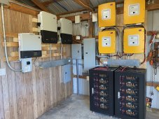
Sorry this went off the SI inverter topic so much. Here's more about my system if there's interest.
 
I'm in process of building a system like this picture that was on a Signature solar Gyll post. They would not give me any info on it, so wonder does anyone know who's system it is and/or how they might be handling the battery BMS to the Sunny Island communication?

madsci1016 are you sill using the smartshunt? I may try to implement your method, although messing with PIs and code is not my idea of fun right now... I have 4 of the gyll batteries and 4 other batteries with a different BMS.... guessing a shunt on the whole battery system would be way to go...???

Thanks!
 

Attachments

  • 1400x1400a.jpg
    1400x1400a.jpg
    322.7 KB · Views: 23
I'm in process of building a system like this picture that was on a Signature solar Gyll post. They would not give me any info on it, so wonder does anyone know who's system it is and/or how they might be handling the battery BMS to the Sunny Island communication?

madsci1016 are you sill using the smartshunt? I may try to implement your method, although messing with PIs and code is not my idea of fun right now... I have 4 of the gyll batteries and 4 other batteries with a different BMS.... guessing a shunt on the whole battery system would be way to go...???

Thanks!

If you look closely at the pic, there's no BMS / data cable coming from the Gylls to the SMAs. They must be using them in Lead Acid mode, which i loathe. Other people live with it though. I have second hand knowledge a Signature solar rep was asked about adding CAN support and SMA protocol and they said they were not interested.

I'm the type of engineer that could design and build an interface dongle to go from Gyll RS485 to SMA CANbus pretty easily though, now that I have done the CAN side. That is if Gyll gave me their protocol and a battery to test on. :unsure::unsure::unsure:

Yes I'm still using my system with Victron shunt / raspberry pi / my driver. It works perfectly (for me) but you are right, it is not for the faint of heart.

It's still on my todo list to go from Victron shunt directly to a dongle and then to SMA to avoid the raspberry pi part. But since i wouldn't use it, it's been low on my priorities. I like all the telemetry from the Raspberry pi / Victron portal.
 
Last edited:
With the threat of the hurricane coming, I finally played around with generator input mode. Since the SIs only have one input, you have to switch it between grid and generator, which is already easy for me as the upstream breaker panel already has a generator lockout plate / connection for a portable generator. I realized setting the inverter to GenGrid input mode (so it does both) was the best option, and where is usually expects to connect to the aux contacts on an external transfer switch to sense which device is active, I just added a switch. So process for me now to connect a generator up to power my house / charge batteries is to just flip the switch and flip my interlock over, and the SunnyIsland will change all parameters to generator without skipping a beat! Woo!

I also added it to my VenusOS driver so now it reports generator correctly and track energy flow correctly.

PXL_20210702_210442289.MP.jpgPXL_20210702_210405364.MP.jpg
PXL_20210702_210412059.MP.jpgPXL_20210702_194526192.MP.jpgPXL_20210702_194521394.MP.jpgPXL_20210702_204519295.MP.jpg
Anyway just sharing my hack for today in case anyone else gets inspired to do it.
 
... and where is usually expects to connect to the aux contacts on an external transfer switch to sense which device is active, I just added a switch. So process for me now to connect a generator up to power my house / charge batteries is to just flip the switch and flip my interlock over, and the SunnyIsland will change all parameters to generator without skipping a beat! Woo!


View attachment 54828
View attachment 54830
Anyway just sharing my hack for today in case anyone else gets inspired to do it.

That puts the onus on you to flip that switch, or else GT inverters (assuming you have those) backfeed the generator.
How about a relay closed by AC present on the generator circuit as the signaling contact?

I though about using a 3-pole breaker so 3rd pole would be the "generator enabled" status, but position of breaker handle isn't compatible with my interlock.
 
That puts the onus on you to flip that switch, or else GT inverters (assuming you have those) backfeed the generator.
How about a relay closed by AC present on the generator circuit as the signaling contact?

I never backfeed the grid, not permitted for it, so it's not a worry. And the real reason for this is the grid input tolerances are so tight by default, the SMAs would never accept power from my generator due to out of spec freq/voltage. So by switching the switch I'm making the SMAs accept the generators power with wider tolerances.

While you concern is valid, I don't think you could even cause real damage to a generator in practice, as if it had locked onto the generator and started to feed it, the generator would quickly overspeed and very quickly the SMAs would detach from it. Even in generator mode i have an issue where as the SMAs start to ramp down load to perform a disconnect, the ramp down is too quick (even at the like 5 seconds it takes) for the mechanical governor on my 15kW portable, and the SMAs end up hard disconnecting before power is ramped down all the way due to over-frequency / over-voltage fault. Though my governor linkage is probably due for a grease job... (I actually had to scratch my head as to why the SMAs were only pulling ~8kW from the generator this weekend, till i had the thought to go whack the governor linkage and sure enough it jumped up to full power drawn. I surmised the SMAs were being too gentle and not pulling more due to low frequency, where as a real brown out would put more pressure on the governor to correct).

BUT i agree always be very careful to not backfeed a generator regardless.

I though about using a 3-pole breaker so 3rd pole would be the "generator enabled" status, but position of breaker handle isn't compatible with my interlock.

Same here, as you can see pictured in my interlock. Hence the second switch.

I'd rather not do the relay as that would mean my system would always "think" i was on generator even during warm up and cool downs of the generator during yearly exercises (or emergency uses) and bin that energy in the wrong category. It's about the data, man. lol.
 
Why not just leave the SMA's locked in generator mode permanently even if connected to the grid?

I think the only difference between the DigIn being open or closed is to give SI's the authority to pump energy back to the grid. Otherwise, if you never feed the grid, what difference does it make?
 
Why not just leave the SMA's locked in generator mode permanently even if connected to the grid?
Well, to repeat:
I also added it to my VenusOS driver so now it reports generator correctly and track energy flow correctly.

But no there more nuance to the different modes with the SIs besides just a wider tolerance in measured parameters. For example in grid mode frequency variations are considered a sign of issues with the grid and cause the SMAs to trip into off grid mode as precaution. In generator mode the SMAs consider that signs of an over/under loaded generator and adjust power draw in an attempt to "regulate" the generator in a sense. They will also more aggressively attempt to balance load between the legs by shifting power between each other through the DC bus, as the detriment of an unbalanced load is more extreme to a generator but not to a grid. You'd be wasting energy in inversion loses if it was left in generator mode and trying to balance the load all the time.

Anyway that's most of the behavioral difference i know of / have observed.
 
Back
Top