diy solar

diy solar

Sunny Island 8.0H-13 + 2x LiFePO4 Weco 5k3 batts

mike01

New Member
Joined
Dec 27, 2022
Messages
8
Hi,

I have a residential solar+storage system.
The house is permanently AC grid supplied.
I have a Sunny Boy 4 with 4.5kW of solar panels.
I have 2x Weco 5K3 LiFePO4 batteries (5.3kw each) attached in parallel (48v) to an SMA Sunny Island 8.0H-13 inverter for storage/own consumption in AC.
As I have a stable grid supply, the SI is not providing backup function.

The Weco batteries were setup for SMA CAN communication (they're not on the SMA supported list but Weco supports the SMA CAN protocol).
CAN communication works (closed loop) and for the majority of time the system and batteries work OK.

The problem:
The Sunny Island is configured to stop discharging the batteries when SoC reaches 20%.
However, every 2 weeks (varies a bit) the Sunny Island goes mad and discharges the batteries to the critical level (5%), BMS protection kicks in and then the whole thing shuts down - SI will not restart charging.
Some images below illustrate this (here a link to the Sunny Island 5 minute log if anyone can have a look at it):

battery drain 1.png

battery drain 2.png


Once the batteries are at 5%, a manual charge of the batteries with a portable 48v charger is required to restart operation.
Somehow the batteries are being drained below the SoC limit in the configuration right up to the shutdown limit.
The installer has tried several settings on the SI but this issue continues to occur.
It seems they have no additional ideas to try and tell me it's a known Sunny Island "AC coupling" issue that can only be solved by wiring 1 solar panel directly to the batteries so that if they are discharged then the panel will bring them back online...


- What could be the reason for the inverter continuing to drain the batteries below its configured SoC limit?
- Any other ideas that could help eliminate this problem?
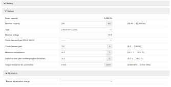
- Could you share the recommended LiFePO4 battery parameters for the setup of the 5k3 with Sunny Island (in Lithium / closed-loop mode)?


Thanks in advance for your support, happy to provide any additional info, BR!
 
Hi Mike,

I observed a similar behavior with my Sunny Island setup where it does not resume charging when SoC level goes below the set point. After further investigation, I realized most charging related triggers are controlled by BMS when “LiIon-Ext-BMS” is selected. So if you want discharging to end at 20% SoC, you may want to program that on the battery BMS. Hopefully your lithium ion battery gives you access to its BMS configuration.

Olu
 
Sounds like you're not closed loop or your BMS is not working properly or need the BMS settings change. Please let us know if you figure it out.
 
Thanks for looking into this and your feedback.
I am trying to get SMA and Weco support to get to the bottom of this and solve the issue. Also contacted forum experts @toms @HighTechLab and @Hedges in the hope they can help.

# Afaik the system is in closed loop - is there a clear way to verify?
In the SI Instantaneous Values I have this below, does it mean the SI cannot control charging via communication with BMS, ie BMS cannot request emergency charging for example?

Screenshot 2023-01-12 121922.jpg


Also I'm sharing below my Sunny Island parameters, the Battery section in full:

1673525240639-png.129209

1673525285414.png
Screenshot 2023-01-12 121136.jpg
Screenshot 2023-01-12 121317.jpg
Screenshot 2023-01-12 121702.jpg
 

Attachments

  • 1673525240639.png
    1673525240639.png
    199.5 KB · Views: 96
I have 5048US and 6048US, have never touched 8.0H.
Also, I'm using AGM, haven't used lithium or BMS.

Does SI report SoC, and is that reasonably correct?
With my AGM batteries, I'm using default SI master relay #2 setting of 70% DoD for load shed, also 80% DoD shutdown.
There can be a second load-shed setting controlling another relay.
Does your 8.0H have the same feature?

Maybe you can configure a load-shed relay to disconnect virtually all loads, or use the signaling relay to switch a thermostat wire, so loads are disconnected such that SI can continue operating without draining battery too far.


Your settings:

Discharge cut-off voltage 46.5; would a higher voltage shut off SI before BMS disconnects?
That probably does not bring AC coupled SB back on line, however.

SI should have a power saving mode where it shuts off, wakes up when the sun should be up. That could avoid draining battery further during the night.
Of course, AC loads have to be less than SB AC production, or battery will continue to drain. That is where load-shed helps.

Is system able to get battery fully charged? If not, it is going to bounce off empty.
Adding PV or disconnecting loads so battery gets full will allow rebalancing, and makes it less likely battery SoC drains too low, although it doesn't fix the particular problem you describe (hopefully keeps SoC from reaching there.)

Lower limit deep discharge 6%; range 3% to 20%, maybe this setting (similar to voltage above) can shut off SI before BMS shuts off.
 
Thanks a lot for looking into this.
I'll do my best to reply/comment below although I have to warn you all I am not a professional...
I have 5048US and 6048US, have never touched 8.0H.
Also, I'm using AGM, haven't used lithium or BMS.

Does SI report SoC, and is that reasonably correct?
Yes, SI reports SOC. Seems to be correct, yes, as e.g. it shows 5% when the batteries' BMS cuts off (and the BMS critical SOC is set at 5%).
With my AGM batteries, I'm using default SI master relay #2 setting of 70% DoD for load shed, also 80% DoD shutdown.
There can be a second load-shed setting controlling another relay.
Does your 8.0H have the same feature?

In my SI the above is set in this part of the config:

1673565892235.png

The above translates to 100-(6+6+8)=80% DoD for load shed, then standby.
Once at 20%, SI stops discharging the batteries (when it doesn't go nuts, as mentioned).

There is only 1 AC connection/relay for shedding load (makes sense?).

Maybe you can configure a load-shed relay to disconnect virtually all loads, or use the signaling relay to switch a thermostat wire, so loads are disconnected such that SI can continue operating without draining battery too far.
Sorry, the above is too much for my knowledge, don't get it.
Your settings:

Discharge cut-off voltage 46.5; would a higher voltage shut off SI before BMS disconnects?
That probably does not bring AC coupled SB back on line, however.
The installer has tried with a higher voltage, we used to have 48v and 48.5v.
Led to the same issue, SI sometimes discharged battes all the way to their BMS' critical SoC of 5%.

Now it is set to below the 48v and still the issue occurs.

SI should have a power saving mode where it shuts off, wakes up when the sun should be up. That could avoid draining battery further during the night.
Yes, but the problem is that it is now even allowing itself to do that - it runs the batteries down to 5% and then will not run/charge even when there is grid and solar power available. Mind you, grid is always available day and night.
Of course, AC loads have to be less than SB AC production, or battery will continue to drain. That is where load-shed helps.

Is system able to get battery fully charged? If not, it is going to bounce off empty.
Yes, I see 100% regularly.
Adding PV or disconnecting loads so battery gets full will allow rebalancing, and makes it less likely battery SoC drains too low, although it doesn't fix the particular problem you describe (hopefully keeps SoC from reaching there.)

Lower limit deep discharge 6%; range 3% to 20%, maybe this setting (similar to voltage above) can shut off SI before BMS shuts off.
It should, but this threshold is being ignored as can be seen in the graphs posted:

1673566543494.png


# Adding another point here, on the relation between BMS critical SOC and SI critical SOC.
Currently, the BMS critical SOC is 5% and SI critical SOC is 20% (6%+6%+8%).
@toms mentioned that maybe a solution could be "setting your BMS critical SOC higher than your SI critical SOC".

I don't have the cable / wifi module so I cannot modify BMS critical SOC.
But if I could set the SI critical SOC to be 9% (3%+2%+4%) and BMS critical SOC to 10% you think it could solve my problem?

Maybe a bit too close? Probably better to have something like BMS critical SOC 20% to 25% and SI critical SOC 10% to 15%?
 
Thanks a lot for looking into this.
I'll do my best to reply/comment below although I have to warn you all I am not a professional...

Yes, SI reports SOC. Seems to be correct, yes, as e.g. it shows 5% when the batteries' BMS cuts off (and the BMS critical SOC is set at 5%).


In my SI the above is set in this part of the config:

View attachment 129316

The above translates to 100-(6+6+8)=80% DoD for load shed, then standby.
Once at 20%, SI stops discharging the batteries (when it doesn't go nuts, as mentioned).

There is only 1 AC connection/relay for shedding load (makes sense?).


Sorry, the above is too much for my knowledge, don't get it.

The installer has tried with a higher voltage, we used to have 48v and 48.5v.
Led to the same issue, SI sometimes discharged battes all the way to their BMS' critical SoC of 5%.

Now it is set to below the 48v and still the issue occurs.


Yes, but the problem is that it is now even allowing itself to do that - it runs the batteries down to 5% and then will not run/charge even when there is grid and solar power available. Mind you, grid is always available day and night.

Yes, I see 100% regularly.

It should, but this threshold is being ignored as can be seen in the graphs posted:

View attachment 129317


# Adding another point here, on the relation between BMS critical SOC and SI critical SOC.
Currently, the BMS critical SOC is 5% and SI critical SOC is 20% (6%+6%+8%).
@toms mentioned that maybe a solution could be "setting your BMS critical SOC higher than your SI critical SOC".

I don't have the cable / wifi module so I cannot modify BMS critical SOC.
But if I could set the SI critical SOC to be 9% (3%+2%+4%) and BMS critical SOC to 10% you think it could solve my problem?

Maybe a bit too close? Probably better to have something like BMS critical SOC 20% to 25% and SI critical SOC 10% to 15%?
Depending on how the BMS works (ie 5% might actually be 20%). You don’t need the SI SOC to be in use, it serves no purpose. As i mentioned to you I have mine set at 1%. (Simply because if my BMS stops charge due to low cell voltage rather than SOC it resets its SOC to zero, and the SI will keep switching off every ten minutes until it’s critical SOC is passed).

Edit: this doesn’t actually solve why your SI occasionally drops below the batteries setpoint, but it may make it so that it no longer matters.

Just make sure your BMS stops discharging at it’s low SOC set point, preferably have a contactor between your battery and SI as a fail safe.
 
There is only 1 AC connection/relay for shedding load (makes sense?).


Sorry, the above is too much for my knowledge, don't get it.

SI has one relay to isolate from the grid when it forms an Island
(6048US does; I think 8.0H does, although I saw something about external 200A relay.)

If there is a load-shed function, may be able to disconnect or turn off enough loads that only SI no-load draw remains.
Yes, I see 1 or 2 stage load shedding in the manual.

Operating manual SI44M-80H-13-BE-en-14 | Version 1.4
Page 32 "Relay1 and Relay2 connections"
Page 48 "6.5.12 Connecting Load-Shedding Contactors"

You can use SI battery voltage through Relay1 or Relay2 as shown to control a power relay, shedding major AC loads.
You could instead wire your thermostat through Relay 1 or 2 to only shed HVAC.
The goal would be to disconnect some or all loads at 20% SoC, such that remaining battery was sufficient to power SI no-load (or with critical loads) until sun-up.
Once shed, the loads will remain disconnected until 20% increase in SoC, i.e. 40% SoC.

Page 87:
"Procedure:
1. Setting the First Level of Load Shedding:
• Select Device > Load shedding 1 > Additional time range.
• Set the parameter Lmt value battery state of charge for start load shedding 1 to the lower SOC
threshold.
• Set the parameter Lmt value battery state of charge for stop load shedding 1 to the upper SOC
threshold.
• Set the parameter Time load shedding 1 and the parameter Start time additional time range load
shedding 1 each to the same value, e.g. to 00:00:00. This will switch the time-dependent load shedding off.
• Ensure that the parameter of the multifunction relay has been set to 1-stage load shedding or 1st stage
with 2-stage load shedding (see Section 7.10.2 "Setting the Functions of the Multifunction Relays",
page 102)."

These seem to be different named parameters from my model. And you get to set start/stop load shed SoC, where mine were 20% apart.
 
Thanks again Hedges.
I went into my SI's config and these are the current parameters that you mention in your post:

1673888404336.png
I'm out of my depth here.
I have a few questions and in general doubt if I can make use of this with my current physical configuration - I think I don't have anything connected to the relays,
I think you would need to have wiring setup for this and possibly an AC power source to be able to charge the batteries when the load shedding is active.
In my setup, permanently grid-connected with no switching, besides the DC connection to the batteries I have the AC2 connection to the home AC and that's it, nothing in the relays (section 6.5.2, page 35).

The SI8.0 looks like this:

1673889774053.png

And my setup looks like this:

1673889690911.png
The requirements to make use of the load-shedding are not met, I guess.
If I change the Load shedding parameters there will be no effect as I have nothing connected to the relay ports.

Thanks again, sorry if this is a waste of your time.
I think for what we've gathered so far a (only?) solution might be to raise the critical SoC on the BMS from 5% to e.g. 20% and drop the critical SoC on SI config from 20% to 9% (minimum).
Then what should happen is BMS stops discharge of batteries when 20% is reached and there's 11% of buffer (from 20% to 9%) before the SI shuts down and I have to manually charge the batteries...
What do you think?
Worth getting a local installer involved to try and rewire this and find another solution to the problem?


Attaching the documentation:
--Manual: https://files.sma.de/downloads/SI44M-80H-13-BE-en-15.pdf
--Quick reference guide: https://files.sma.de/downloads/SI44M-60H-80H-12-IS-xx-13W.pdf
 

Attachments

  • 1673889102868.png
    1673889102868.png
    552 KB · Views: 3
Your SoC based settings are same as mine (default)
The time of day settings I haven't done anything with.

As I understand, your inverter is supposed to shut off at some SoC but it apparently keeps operating and draining battery. I don't know why.

If you added a load-shed relay, that would disconnect all loads at 30% SoC, so even if inverter keeps running it might not (given enough battery) drain to the point where BMS shuts down.
If you have AC coupled Sunny Boys, those remain connected directly to SI, and only loads are shed by a relay.
 
May be you can try to set up the SI and use the grid as a generator. After let say the SOC drops below 30%.
 
Hi @penandpike, thanks for the suggestion. I already mentioned that to my installer, says it's not possible / might be possible with a switchover box, it's an out of proportion solution for this apparently.

I've had WECO the battery manufacturer have a look at the batteries via their BMS tool.
Cells balanced, communication via CAN with SMA protocol OK incl. SoC passed on to the inverter, everything fine apparently.
Here's a shot:

1674218959754.png

I still cannot get a clear answer from them on what triggers an emergency charge request.
WECO says in the case of SMA protocol, the emergency charge request is triggered by the BMS on the basis of voltage, not SOC %. I thought the trigger would be cell voltage at or below 2.9V which times 16 cells would be around 46.4V but they say it's below that - I asked them to specify what is the threshold, got no reply yet - could it be 44V? Another possibility is that the BMS' request charge feature is not working and it has to be the inverter supplying charge.

# And I've been playing around with Sunny Island Battery parameters:
Can now say that the Discharge Cut-off Voltage parameter doesn't do anything in my case (if you set it above the battery voltage it doesn't stop discharge or trigger charge, has no effect). Suppose because I have the Sunny Island in Li-ion mode and it is driven by the BMS-provided SoC %.

# Also had a deep read of the Sunny Island manual regarding the parameters for battery management via SoC %. SMA is awful at explaining.
My installer was not understanding what he was doing because he didn't take the time to understand it properly.
As a way to return something, here is a Google sheet with something which makes it easier to understand and test the behaviour, hopefully.

# And another thing I did was dive into the Sunny Island 5min file where I have 2 occurrences of the battery run down logged, on 24.11.2022 and 05.12.2022. Colour coded the battery voltage, SoC % and battery charge/discharge current.
Before each of the failures, there are several days of low PV production with the batteries at relatively extended periods (1 week or 2) without a full charge and on the low end of the SoC. It seems the same SoC communicated to the inverter by the BMS becomes associated with lower and lower voltages as days go by - this is something that should not be happening I guess? Anyway, voltages become lower and lower for the lower end SoC limit until at one point they just drop quickly and there is no attempt to start an emergency charge.

In my case, when the failures happened, the inverter did nothing of what it was supposed to do; there was no attempt to charge the batteries even though SoC fell under the threshold for utility grid charging and utility grid was available at all times; it was set to trigger below 10% in this occasion, went from 16% to 15% then suddenly to 10%, then 6% and 5%... no attempt to charge:

1674229893355.png


Thanks to all for your inputs so far.

Contact with WECO batteries was not helpful, bascially they shrugged off responsibility and don't provide critical information.
SMA are taking weeks to reply to my support request.
Will report back if it makes sense...
 
Looking at the graphics above it seems very strange that the SOC drops very rapidly. It looks like the SI had entered Protection mode level 1 because there is no discharge and no decline in the SOC but suddenly there is a drop and then another. It is like the SI is not doing anything but the BMS keeps changing the SOC. Are you sure that there isn't something draining the battery besides the SI? Looks like something is going on with the battery (may be the capacity is different) so the BMS freaks out. (let say BMS expect 100Ah in the battery so when you drain 70Ah the BMS will indicate to the SI that the SOC is at 30% , but what if the actual capacity in the battery is only 80Ah Then the voltage in the cells will drop and that may trigger the BMS to change the SOC by some algorithm). The graph that you posted in your last post says that the SOC is 24% and that the cell voltage is around 3.16V and charging with 30A. You know 3.16V per cell is more likely something like 14-15% not 24% and if you put some load ( instead of charge ) on this battery the voltage will drop even more. I would guess that the actual SOC at the moment when this data was taken was not more then 5-10% Something could be wrong with the BMS too but I doubt it.
I see no reason why you can not use the grid and connect it to AC2 and simulate it is a generator.
 
Last edited:
Hi!
Replying to your comment:

Are you sure that there isn't something draining the battery besides the SI?
Yes, 100% sure nothing is discharging the batteries besides SI - they are connected only to SI and SI should not allow discharge for AC consumption. (Of course, maybe SI is allowing discharge for AC consumption due to some stupid, software-related reason which I can't verify or understand).

I've finally managed to speak with SMA support.
The explanation SMA gave me for these wild SOC fluctuations and the jumps/rundowns is the way SI calculates SOC and the SOC error... apparently when it felles it needs to recalculate SOC, it can lead to behaviour like this... either that or faulty cell in the batteries or bad BMS (doubt it).
They told me to go the SI config and start a new battery setup process which I did. The key value they mentioned was the C10 discharge parameter, which I managed to get from WECO: 200Ah.
It was previously set at 206Ah so doubt that will solve the problem, just a matter of time until it happens again.
They said if this keeps happening then they can send SI log data to HQ in Germany for deeper analysis.

I'll post again if I have news. Thanks for all the help!
 
I don't think SI is discharging the battery. I think that the battery capacity is less then the BMS "thinks", it is! It is the BMS that is changing the SOC (without SI discharging it) and there is nothing the SI can do to stop that. I don't think that the problem is in the SI but in the battery and the BMS configuration.
 
That is definitely one of the posible scenarios.
I think Si is not discharging, but also unsure if it's the BMS or SI creating the crazy jumps in SoC.
I couldn't get a straight answer from the SMA support person but do you or anyone know 100% sure if SI is receiving and using the SoC value provided by the BMS or is SI performing its own calculation of the SoC value?
From my call with SMA I got the impression that SI always uses a SoC value that it calculates and that it has a high "SoC error" associated with it, up to 8% they said. Puzzles me how that is the way it works in the li ion mode with a battery with BMS (Si should simply rely on BMS-supplied SoC) , but the technician was basing his explanations on the SoC error, etc.
 
When in LI ion mode SI doesn't calculate anything and rely on the BMS. I think that if you change the BATTERY CAPACITY VALIE for the battery in the BMS settings (lets say -15% of the current value or make a capacity test to know the exact number of Amps(KWh) in the battery ) . this problem will not happen anymore.
 
Last edited:
Does SI have any parameters it uses to determine empty battery independent of BMS?
When I use VRLA settings (for AGM), it measures amp-hours, but also have voltage readings. I would imagine using BMS it might still shut off at some low voltage.
 
Hi hedges,

The SMA guy told me the key parameter is the nominal capacity of the battery (C10 according to him). In my case, with 2x 5kwh units, it's 200Ah (which times the fixed, predefined voltage of 48V that SI assumes in Liion mode amounts to 9600Wh - that is conservative as the nominal capacity is 2x 5.3kwh in my case).
In the 5min file post above you can see it reads a lot more parameters incl the battery voltage. And in another post above I posted all the configuration parameters for the battery section, there is e.g. Discharge cut-off Voltage. But from my experience this is ignored in Liion mode, does not control behavior, based on analyzing my 5min file during the battery run downs it just ignored the cutoff voltage, should have stopped and didn't (or BMS was giving an erroneous voltage reading... Also not sure if the value is provided via CAN or if it's an actual voltage reading by Si) . The problem is that it's all a big black box, the documentation does not tell you what SI is using or doing in Li ion mode.
 
Back
Top