Sorry for my delay, family matters. I'll see if I can answer some of these questions/concerns. Thanks for all the quick replies.
@Hedges is the SMA Guru but...
I have to ask, you got these off of eBay but have you seen them powered on before?
Did the seller post pictures of them powered on?
My first though based on your description is that the Mosfets are shorted. I would not try to power it back up unless you can disconnect the capacitor bank once it's discharged and directly check the DC input side of the Inverter board to see if it registers as a dead short with an Ohm meter with NO power attached.
No, I did not see them powered up. purchased from two different sellers. I don't think I have that bad of luck, two bad units from different sellers. I will need to research so before trying your suggested test. Thank you.
If you blew all the class t fuses I wonder if you welded all the BMSs closed.
The BMSs should trip in microseconds and the class-t fuses should blow in milliseconds.
I would test the BMSs to see if you can administratively disable the discharge paths.
I was able to turn charge and discharged off within the app. after turning off SI breaker. All BMS's seem to be functioning correctly.
Is he saying the Battery is no longer working after he reset it?
Batteries/BMS's seem to be fine.
I believe the SI capacitors are after the breakers (another forum member claimed otherwise.)
So I think you need to close all the breakers, then apply precharge, then fully connect.
SI consumes 4W when not inverting, so you might choose a precharge resistor (or length of wire) appropriately.
One member did blow class T fuses and well external BMS relay with the SI capacitor charge surge.
It should power up fine with four car batteries in series. It is just these newfangled lithium batteries that keep having problems. But a suitable precharge circuit ought to make it work.
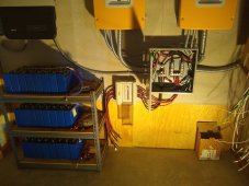
First try; I used a 100w 50ohm resistor and connected it from battery positive to positive bus bar (before class t fuse). Left in place for about a minute, removed it and with-in a few seconds turned on one battery breaker and then the SI breaker.
Second try; same as first but used turn on all three battery breakers. I believe this is when I blew the fuses.
At this time, I don't have any lead batteries to try. I would have to take them out my in-law's RVs.
To precharge my si inverter I held the resistor in place across my main power breaker for several seconds until it went into stanby mode. Then before removing the resistor from the main breaker I would engage the main breaker. If the op is removing the resistor before engaging the main breaker the capacitors will start to discharge and cause the surge when the main is closed. This is my experience anyways. Hope this helps.
Are you referring to the main breaker of the SI or the battery breaker?
The purpose of the DC capacitors on inverter input are for high frequency PWM filtering. It would diminish their effectiveness to put them before the internal breaker with the extra wiring and breaker inductance. The input capacitors need to be close to, and minimum resistance/circuit inductance to the switching MOSFET's.
I do not know if the SMA internal breaker is an actual breaker or just a switch. A breaker typically has a short circuit current trip mechanism that is a series connected magnetic solenoid coil that adds inductance (and some resistance) to breaker.
High current DC breakers add a significant series resistance to battery cable path. Typically, 3 to 5 milliohms.
Try leaving the internal breaker/switch on when pre-charging inverter capacitors. If switch is before capacitors, which is really the only logical configuration, then having inverter switch open will not be allowing any pre-charging of internal capacitors. Then your BMS trips for high surge current.
According the SMA's webinar for the SI the DC breaker on the front is an ON/OFF switch for the DC side but voltage can still be present in certain locations.
Leaving the breaker/switch on seems like a logical step but there seems to be some debate on this subject.
I guess your dad "knew you'd have to get tough or die"?
What size were the Class T fuses?
Good catch, I generally have to explain my screen name.
300amp class t fuses. The blew once I had tried the SI with all three batteries on.
Unfortunately, due to the way the Sunny Island manual is written, it gives users the idea that the breaker on the front panel is an ON/OFF switch that cuts power to the Sunny Island. It does not. SMA really goofed with the way they wrote the manual in that regard.
Leave the Breaker in the OFF position when you precharge. When precharge cycle is over, engage main battery contactor, then turn the breaker on starting with the slave first (if present) 3 second pause, then the master.
If that doesn't work, I suggest you try connecting the Sunny Island directly to your battery terminals and bypass the BMS, if it starts normally, then it's your BMS.
My guess is that your BMS is the problem.
Yes, as stated above the SI DC breaker/switch is a little confusing. On page 68 of the manual, it states the following:
7.2 DC Circuit Breaker
The DC circuit breaker is used to switch on/off as well as to disconnect the Sunny Island on the DC
side (see Section 9 "Switching On and Off", page 75).
But as I stated above the webinar states it should be treated as a DC disconnect as voltage can still be present.
The start-up procedure you describe is what I was trying.
Didn't think about by passing the BMS. As no charging is being done what are the potential risk? Nothing to limit current as it stands the BMS's limit each bank to 100amps.
What do you think is up with the BMSs?
I believe breaker on front panel does cut power to Sunny Island (and therefore must be closed during precharge OP needs to do.)
Why do you think otherwise?
I tried to measure capacitor value. With breaker open, no significant capacitor. With breaker closed, over-range for my meter.
Pretty much the definitive answer. Internal switch OFF, no internal capacitor pre-charging will happen.
As I stated above debate on the subject. SMA manual page 68:
7.2 DC Circuit Breaker
The DC circuit breaker is used to switch on/off as well as to disconnect the Sunny Island on the DC
side (see Section 9 "Switching On and Off", page 75).
Webinar states voltage can still be present in places. So, is there an electrical path around the breaker/switch to the capacitor bank? This seems to be the 64 dollar question. Does someone want to tear apart their SI to fine out?
Once again thanks for the replies.