diy solar

diy solar

Switch question

GGameBoy

New Member
Joined
Feb 22, 2021
Messages
63
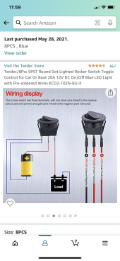
I bought these switches to turn on a small light but after installing them the light did not turn on. The only difference in the wiring from the picture is instead of attaching the load negative to the switch I attached the negative to the battery negative on the fuse block. Would that cause a problem? Or do u think its a bad light or switch?704F0104-2EFB-4CE1-86F9-7BE7A257A2B6.png
 
When it is in the on position, there should be a short between the load and power.
If you have a meter, it's pretty easy to tell if it is a defective switch.

Just measure with the switch on, from the negative to either the load or power lines, you should measure 12v.
With it off, you should measure 0v from load to ground.

Hopefully you wired it into the fuseblock so you could make sure it is fused. Check the fuse.
 
If the light is LED, it can be to sensitive how you wired it. I have LED strip lights that if I swap the + and -, they won't work.
 
Last edited:
A better way to imagine the diagram you posted is to replace the battery symbol (the yellow and black battery symbol) with your DC fuse block. The positive end of the battery in the diagram is your light fuse connection. The negative end of the battery in the diagram is the negative bus bar of the fuse block. The load symbol (the black load symbol that confusingly looks like a 12V battery) in the diagram is of course your light.

Here's how I would debug the problem. First, completely remove the switch. Test the light by connecting the pos and neg wires from the fuse block to the light. If the light works now then you know that's not the problem.

Now try the switch again. Run the positive wire from the fuse block to the switch center pin. Then the wire from the positive lead of the light to the other positive pin of the switch. Then run the two wires to the negative pin of the switch. One from the negative lead of the light and one from the negative bus bar of the fuse block.
 
Last edited:
A better way to imagine the diagram you posted is to replace the battery symbol (the yellow and black battery symbol) with your DC fuse block. The positive end of the battery in the diagram is your light fuse connection. The negative end of the battery in the diagram is the negative bus bar of the fuse block. The load symbol (the black load symbol that confusingly looks like a 12V battery) in the diagram is of course your light.

Here's how I would debug the problem. First, completely remove the switch. Test the light by connecting the pos and neg wires from the fuse block to the light. If the lights works now then you know that's not the problem.

Now try the switch again. Run the positive wire from the fuse block to the switch center pin. Then the wire from the positive lead of the light to the other positive pin of the switch. Then run the two wires to the negative pin of the switch. One from the negative lead of the light and one from the negative bus bar of the fuse block.
Yes, rather stupid and confusing that "load" is a battery symbol.
It takes a second to grok drawn that way.
 
Back
Top