Owlbawl
New Member
Hi, tried to search forum but didn't find clear answer for me.
Had to use Solar inverter with LiFePo4 battery attached to it because of regular power outages in my place.
Would appreciate for your help and advice!
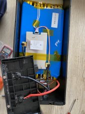
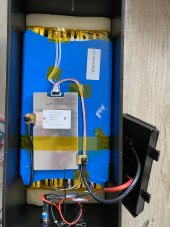
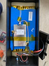
Just bought Must PV18-3024 (3kW) solar inverter on Aliexpress, where I've also got the Lifepo 24V 100Ah for it from "KEPWORTH".


Battery was once tested with 100A load (2400W) for 1 min (had flashing low voltage alert on inverter, but hold).
For now I had two ~50% discharges on 0,1-0,2C for about 3-4 hours outages.
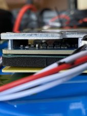
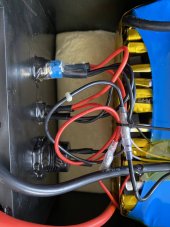
Battery is connected with 25mm2 ( 4AWG ) copper cable.
The thing is kinda make me worry - is the state of the battery I bought.
When inverter switch to battery - both times I saw starting voltage 26,2 and 25,8 at the end of cycles. With 200~400W average load (about 0,1-0,18C).
Made manual load test (can't attach the screen video I've made):
Made control measurement with voltmeter on battery terminal with it disconnected from inverter, was showing 26,7V at start (battery not fully charged).
The inverter itself shows 26,6V
Switched off the grid - load 200W - voltage dropped to 26,2V // 250W - 26,1V
When I connect 1000W load - I see the voltage drop from 26,6 to 25,6.
Is it normal behavior for "new" LiFePo 8s with BMS? Or it could be showing it made of degraded / used cells?
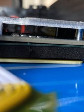
The case is glued, so no chanse to measure the inner resistance / voltage on cells without damage disassembly of it...
Had to use Solar inverter with LiFePo4 battery attached to it because of regular power outages in my place.
Would appreciate for your help and advice!
Just bought Must PV18-3024 (3kW) solar inverter on Aliexpress, where I've also got the Lifepo 24V 100Ah for it from "KEPWORTH".
Battery was once tested with 100A load (2400W) for 1 min (had flashing low voltage alert on inverter, but hold).
For now I had two ~50% discharges on 0,1-0,2C for about 3-4 hours outages.
Battery is connected with 25mm2 ( 4AWG ) copper cable.
The thing is kinda make me worry - is the state of the battery I bought.
When inverter switch to battery - both times I saw starting voltage 26,2 and 25,8 at the end of cycles. With 200~400W average load (about 0,1-0,18C).
Made manual load test (can't attach the screen video I've made):
Made control measurement with voltmeter on battery terminal with it disconnected from inverter, was showing 26,7V at start (battery not fully charged).
The inverter itself shows 26,6V
Switched off the grid - load 200W - voltage dropped to 26,2V // 250W - 26,1V
When I connect 1000W load - I see the voltage drop from 26,6 to 25,6.
Is it normal behavior for "new" LiFePo 8s with BMS? Or it could be showing it made of degraded / used cells?
The case is glued, so no chanse to measure the inner resistance / voltage on cells without damage disassembly of it...