diy solar

diy solar

Testing JBD 150a V1.5...Low Temp Cut-Off Issues..HELP!!

CaseyB

New Member
Joined
Dec 7, 2020
Messages
78
I just received 5 JBD-SP04S005 V1.5 BMS's with the uart to usb adapters from the vendor "Minerals" off AliExpress. They came well packaged and the shipping was from DHL. Included were the harnesses as well as 9 external NTC's (one was missing)...more about those later. I haven't ordered my LFP's yet, so I set up a "battery" with alkaline D-Cells and a Mean Well HRPG-150-3.3 power supply...

205ABAAC-F4F3-4269-941A-4D335F92CF7C.jpg

... I wired 3 sets of 2 D cells in series to stand in for LFP cells C0 thru C2, I'm using the Mean Well supply for C3. Having the supply as C3 allows me to test LV and OV cut-offs. Not seen are the 2 DVM's, one connected across the +/- terminals of the power supply and the other connected between + on the power supply and C- on the BMS. I added the 1.1k resister between C- and B+ to give a small load to the discharge fets to over come fet leakage (without the resistor it would show battery voltage on my DVM regardless of on/off state). The cup to the right of the BMS is a salt water brine left in the freezer over night for the low temp cut-off test.
I switched back and forth between the open source BMS-TOOLS , and the official JBDTools to read/write to the BMS. I much prefer BMS-TOOLS, it is way cleaner, but it doesn't have as many configuration options..I don't know if that is an issue or not.
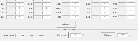
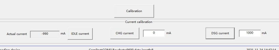
Here is a screenshot of BMS_TOOLS configuration page...
BMS-Tools Config.png
...and here is JBDTools Configuration page...
JBDTools Config.png
...you can see there are more options in the JBDTools "Function Configuration" box. Back to BMS-TOOLS, here is a screenshot with everything normal...
BMS-Tools Normal.png
...with LV cut-off...
BMS-Tools LV.png
...and OV cutoff...
BMS-Tools HV.png
At this point I'm doing the happy dance...alas, it was not to last. Here is the low temp test...
BMS-Tools LT.png
You can see the brine dropped the thermistor to -3.6C and the charge fet did not disable... no love. The other anomaly is even when I uncheck the "NTC2" box the second temp still shows, I assume the second temperature is the fet temp. I have tested all the read/write functions and they all seem to work. All 5 BMS's tested exactly the same.. I'm hoping it's as simple as not checking a box in the "Function Configuration". As all of them tested the same it seems unlikely that there is physical damage to all of them. Could it be the "RTC" box that shows up in JBDTools, but not BMS-TOOLS ? I'm a little reluctant to start clicking things on without actually knowing what they are.
The second issue is with the plug in NTC's that came with the BMS's. The BMS pins that the NTC's plug into are clearly labeled with H+ and H- on the ends...

E13C3E6D-A492-4F5D-9BFC-0B7D267463F7.jpg
... I have read elsewhere that is switched heater power triggered by the NTC temp. The NTC connector on the left is how they were configured when I received them and the one on the right is the one I swapped pins on to match the boards. Am I correct to do this?
1BF51F45-E6D8-4F7D-80CB-97CEA181F183.jpg

Any help the brain trust here could offer would be much appreciated.
 
Nope...checking the "RTC" box didn't work...Bloody 'L. Not having low temp cut-off isn't a total deal breaker for me, but it is beyond irritating.
 
I think you need actual charging to be present for the low temp protection to kick in. Same for discharge low temp protection. I did with my V1.3 boards.

The heater connections are still a mystery as far as I know. I wouldn't change the order of the wires until more is known.
 
Thanx WingNut for the reply,

I considered that, and it may well be the case. What seems odd to me is whether there is a load (resistor) or not the the software indicates the fet condition on LV and HV cutoff, in other words it shows the fet was told to turn off whether there was current flow or not. Now it is well within the realm of possibility that the low temp cutoff has to have actual current to cut off.

Did you confirm that the low temp protection cutoff didn't work without an actual charge?
 
Looks like you were right Wing nut. Here is the messaging to/from the vendor..


8431F3E6-1AC1-4DA4-BE55-8C2C4B237911.png

E0CD95CD-9383-4C14-A0DA-4F10A3A2FA32.png

I won't have any cells to do an actual charge test for months so I guess this will have to be my answer.
 
I remeber to read a post about this temperatur cut off, the cut off only happen when a charge current is applied. The BMS need to detect a charge surrent before cutting it.
 
Thanx lexa,

You make the third source to point this out..I need to learn to take "yes" as an answer.
I also need to make a shout out to "Minerals Store" on AliExpress. Funky name but but very speedy and responsive.
 
Thanx WingNut for the reply,

I considered that, and it may well be the case. What seems odd to me is whether there is a load (resistor) or not the the software indicates the fet condition on LV and HV cutoff, in other words it shows the fet was told to turn off whether there was current flow or not. Now it is well within the realm of possibility that the low temp cutoff has to have actual current to cut off.

Did you confirm that the low temp protection cutoff didn't work without an actual charge?
Yes. Both charge & discharge low temp protection didn't work unless actually charging or discharging. You can temporarily change the temperature set points to facilitate the testing to confirm basic functionality.

I worked with alkaline batteries for all that initial testing also, 8 AA batteries for me. Alkaline batteries can be charged with controlled voltage and current. It's not a recommended practice but will get you through the testing of all 5 of your boards.

J2 is the designation of the heater connections. I was told:
J2-1: Positive for heater
J2-2: Negative for heater
J2-3: temperature switch
J2-4: temperature switch

Sid was just working from memory here: https://diysolarforum.com/threads/jbd-150a-smart-bms.5855/page-2#post-226562 & and not actually looking at the heater harnesses.

It should be fairly straightforward testing for voltage on the heater harness with the heater temp sensor in your brine solution. It would be great to confirm the order of the wires etc. If I find out the max wattage for the heat pads or on/off temperatures I'll post it. My V1.3 boards don't have the heater connections so I can't do any testing to help out but am very interested in getting the info.
 
It's likely a temperature switch and not a temperature probe on the 4 wire connector. Probably not a good idea to put the switch directly in brine. On https://www.wohnmobilforum.de/ I found this link: https://drive.google.com/file/d/1WWIoawTwGnlkrRYxR4b7H3B0cFgkGjOZ/view

If it is a temperature switch as the doc shows then multi-meter probes on J2-1 & J2-2 should see battery pack voltage if:
J2-1: Positive for heater
J2-2: Negative for heater
J2-3: temperature switch
J2-4: temperature switch

If:
J2-1: Positive for heater
J2-2: temperature switch
J2-3: temperature switch
J2-4: Negative for heater
then multimeter probes on J2-1 & J2-4 should see battery pack voltage

There are photos on the internet of it wired both ways. Could be different version number boards & sure is confusing.


& https://www.wohnmobilforum.de/bilderdienst/wohnmobile/Bms-mit-Kabelset_10874_70a8.jpeg
 
From the document in the previously posted link:

Heating on condition: Low charging temperature protection occurs (can be set), and the charger is online

Heating off conditions: Charging low temperature protection recovery (can be set)

First, does charging have to be present to meet the Heating On condition?

Also, it's not clear to me if Heating On and Off is affected by low temperature protection and recovery settings in the app or not. We know that low temperature protection and recovery can be set in the app. If the heat pads are turned on & off by a thermal switch then it seems to me that is independent of app settings.

It would be nice to know if low temperature protection and recovery settings in the app affect the heating circuit or not.

Heating circuit limiting current: The maximum current limit of one port is less than 2A

This indicates that less than 2A per port is permitted but are the PCB traces shared? Is it less than 2A if only one port is used but also less than 2A if both ports are used?

Limiting the heating pad to 20W if one port is used and 10W each if two ports are used seems to be best until this heating option is better understood.
 
Interesting. I really don’t need battery heating ( batteries will be in living space) but it would be good to know if the function works. These “switches” appear to be a Chinese dealyabob..searching the part number come up with Chinese only web pages.

Something else to play with.
 
Thanks for all the previous information. Here is an update on what I have found:

It's likely a temperature switch and not a temperature probe
This is correct. It does not look like an NTC device. The temperature sensing device on the pigtails for my V1.5 board I recently received are labeled as BH05-BB5D 35C. This is a NC temperature switch that opens at 35C (95F). I confirmed this in the toaster oven before my wife woke up, :cool:. I think this would act as an over temperature protection for the heating device. That makes good sense from a safety perspective.
The second issue is with the plug in NTC's that came with the BMS's.
They are temperature switches, not NTC's

If the heat pads are turned on & off by a thermal switch then it seems to me that is independent of app settings.
This is not the case. The heating power is turned off by a thermal switch at 35C as a safety precaution. I believe normal cycling is done through the BMS settings

This shows the heating function activates at the low temp charge protection setting and turns off at the low temp charge protection release setting.

Also, it's not clear to me if Heating On and Off is affected by low temperature protection and recovery settings in the app or not.
I believe this to be true.

Also, The Minerals vendor on Aliexpress says "Power no more than 10W" for each heater port. So two 10 watt heaters total, one on each port, or power a relay if you need more heating.
 
I swapped pins on to match the boards. Am I correct to do this?
I would not recommend swapping pins on the connector. The center two pins are connected together, you can see the trace on the board and I tested this. Swapping as you show will disable the over-temperature protection.

J2-1 is full pack voltage. I believe from the B+ plate on the board. This is connected to the + of the heater
J2-2 is negative of the heater
which is directly connected to
J2-3 is connected to one side of the NC temperature safety switch
J2-4 is connected to the other side of the NC temperature safety switch

When the BMS grounds J2-4 based on the low-temp cutoff settings, the circuit is powered on.

I'm too lazy to make a diagram, but it is pretty simple.
 
I did not expect the temperature switch to be a safety Off switch! Is there continuity between J2-2 & J2-3 when nothing is connected?

The Off safety switch does make sense. It's important to have. 35C seems high for heating so it seems that it is dual purpose maybe. For DIY, I had thought that two low temp On switches in series would be a good safety precaution. If one were to fail closed then the other would still open.

It is looking like there's app control of heating ON & Off. Can it be confirmed by just setting high enough temperatures in the app (so using ice packs etc. not needed)?

Thanks for the info.
 
I'll test this out today.
I put the NTC temperature probe (not the NC temperature safety switch on pins 3 and 4 of the heater harness) in a bag of ice, and both heater circuits had power come on at and below the undertemp charge protection trigger of 30F. The heater circuits turned off when the probe passed above the undertemp charge protection release of 46F (for testing). So it the heater circuits work fine right out of the box with the supplied pigtails.

As a side note, I also discovered that I had trouble setting my BMS protection temperatures in Fahrenheit. I had to change to Celcius, set my temps, then switch back to Fahrenheit.
 
Great info here on this BMS. I ordered two and am planning the install. What is the diameter of the holes in the B-, C- and B+ copper plates? I cannot seem to find the info on the Jabaida page on Alibaba.

Thanks in advance
 
Newby here.
Got myself a JBD SP04S034 4S 200A which has a heater pad port.
For testing purposes, I made a quick 12V Lifepo4 pack using 32x used A123 cells.

I ran through the same situation for the under-temperature charge cut-off feature, just couldn't make it work, been on it for 2 days.
Got the over temp feature did work on the discharge FET.

Finally got it to work after I played around with the 'CALIBRATION' settings for the CHARGE and DISCHARGE current.
Quickly measure the charge current and type it in then press the button next to it. Did the same thing with the discharge current.

After I did that, I supply a charge current and brought the external probes to the temperature range as in the settings, the CHARGE FET turned OFF and the heater pad output turned ON
I still got to figure out if the Discharge setting has anything to do with it or not.

Another thing about the discharge calibration I don't understand is the accuracy.
With a load at the output and no charge current, I measured the load to pull 3050mA which I input to calibrate: The actual current draw is displayed is -890mA. I then tried a 1000mA actual load and calibrate using that new current, the ACTUAL CURRENT is now displaying -990mA.
Still trying to figure that one out. Doesn't make sense to me that the accuracy should be that screwed up. maybe it is just to get a trigger current sense for the protection to kick in...IDK
 

Attachments

  • Capture4.JPG
    Capture4.JPG
    52.4 KB · Views: 4
  • Capture5.JPG
    Capture5.JPG
    31.4 KB · Views: 4
Back
Top