diy solar

diy solar

Testing Metal-Oxide Varistors (MOV)

Hedges

I See Electromagnetic Fields!
Joined
Mar 28, 2020
Messages
20,504
Surge arrestors are used on AC and DC side of PV inverters for protection, to clamp high voltage transients.

One inverter I have (actually several) are in the SMA family SUNNY BOY 5000-US / 6000-US / 7000-US / 8000-US. These come with a kit of MOV to protect the DC side:
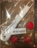
SMA DC Varistor kit IMG_1103.jpg

The MOVs are about 20mm in diameter, and the three are held in sockets, not wired in parallel but rather in a delta. I think one is across the PV input, and one from each of the PV inputs to chassis.

SMA manual says if damaged for for periodic maintenance in lightning-prone areas:

"replace all DC varistors:
Only use spare parts from SMA
• Always replace the entire set of DC varistors.
• Order number in Section 12 ”Spare Parts and Accessories” (page 101)."

They are conveniently devoid of any markings. Or more likely, SMA paid extra to get them unbranded.

I've got a HyPot, so I connected that and cranked up voltage until it tripped for 1 mA leakage. The three parts were all about 760 VRMS, more or less, which is 1075 V peak.
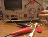
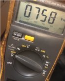
HyPot MOV IMG_1114.jpg VAC MOV IMG_1117.jpg

Not what I expected - thought it would be much closer to the 600 Voc max spec of the inverter.

Could be the following part, min voltage meets my measurement:

Or this one, typical voltage matches (but color is differnt):

These are recommended for 970VDC or 895VDC, would have expected something lower.

I plan to add more, rated for lower voltage and higher energy.
 
Looks like I never posted my results testing another TVS system.
I was looking into making my own, same functions as Midnight offers (status lights)


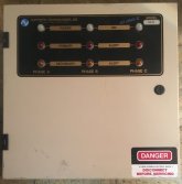
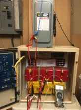
But bought a new old stock 3-phase unit instead. Here's the inside, together with my tester:

surge arrestor IMG_1052.jpg test surge arrestor IMG_1060.jpg

Couldn't directly apply the HyPot from previous post, because these large cans with many MOV inside present too much capacitance (80 to 90 nF); before Vac gets high enough for the MOV to fire, current required to drive capacitance at 60 Hz exceeds 1 mA and it trips.

So, I used a resistor and 12kV diode meant for a microwave oven to charge a capacitor. Had to turn HyPot voltage up very slowly to avoid tripping. With 600 Vrms charging cap to about 900Vdc, throw the 600VDC disconnect switch and apply voltage to surge arrestor.

trace surge arrestor IMG_1064.jpg

Voltage rises sharply to 200V, then is clamped.

This unit is now connected to my split-phase utility connection.
It has 6 awg connections, and two stages of MOV each protected with 30A fuse. If lower voltage blows, slightly higher one is next line of defense. Status lights show power and if either MOV on a phase has shorted. It has dry contacts to send alarm.
 
Hello Hedges,.

So did you test the lower voltage MOV's that you linked?, im interested in your findings as i have some 120V DC equipment conected to long lines of cable, i should put some protection, but most SPD's for DC are around 600V or more.

An about solar... I guess for inverters without that protection phase... you can simply add some AC and DC SPD's before the inverter achieving simillar results?. I think SPD's are just MOV's inside, but never opened one.
 
I read that long lines can have voltage induced by nearby lightning strikes.

I haven't tested the Midnight units or bought any individual MOV.

I think it was Midnight documentation that said their AC units could be used on DC, but some status indicators wouldn't light - LED only turns on for one polarity. The MNSPD-115 is recommended for DC up to 115V. Spec shows MCOV 180V, which I read is maximum continuous RMS (not peak) voltage.


A MOV by itself, when it fails, goes shorted. Perhaps that can safely clamp a PV string, depending on current capability? That appears to be how SMA used them. In the case of AC, it will never pull down the utility grid, so something needs to open. Fuses are one way, and voltage across the fuse can light a failure indicator. There are some 3-terminal MOV with thermal protection device, which can be used that way. I think MOV with thermal protection would be the way to go for DIY, unless you added a fuse. Otherwise, would probably overheat.
 
I read that long lines can have voltage induced by nearby lightning strikes.
Yeah thats what im worried about!

Your linked SPD could work, however there is 4 x 120V lines, so using midnights would trash the wallet, need to find something cheaper and more compact.

I will check what type of internal circuits the midnight's have, if they are simillar to the DIN rail solutions that i have see.. maybe the DIN's could also work for DC. They are much cheaper and compact.

Very simple inside, no MOV's! :

A MOV by itself, when it fails, goes shorted.

Thats where the lack of electronics knowledge hurts, i tough MOV's opened the circuit, so my idea is not going to work (Probably)

There are some 3-terminal MOV with thermal protection device, which can be used that way. I think MOV with thermal protection would be the way to go for DIY, unless you added a fuse. Otherwise, would probably overheat.

Will check this ;)
 

Ten of them for $20.47 plus shipping. Can your wallet handle that?

I would use three to protect PV positive and PV negative to each other and each to ground. (At least for my application, which has PV leads either floating or at least not hard grounded.)

I started to design around that part, including LED to indicate both "power on" and "failed", realized I had to be careful my design could bring line voltage to an LED, so only its molding compound and bezel stood between that and people. Buried in a transparent jar like Midnight design avoids the issue.

You can just connect the parts. But if you don't know they sacrificed themselves to protect your equipment, protection is lost. SMA recommended some replacement schedule if in lightning-prone areas.
 
Sounds reasonable.
Would think TVS should be higher clamping voltage than MOV, so after a delay MOV takes over.
PV DC varies by system. AC typically 120V, 220V, some others per phase. 48V or other. I would design protection at several voltages.

Series inductance and resistance can limit current and reduce risetime, especially in conjunction with capacitance.

Line to line and each line to ground is good. I realized that was missing when I put Delta on PV of my transformerless Sunny Boy. I wanted to clamp above 600V differential and either to ground (due to power-one test sequence of inverter.) The suggested higher voltage parts and configuration didn't do that. Then my measurements said the device didn't protect anything at all.

Would be good to have a pulser able to test it. I used HyPot or visible blade switch to measure trigger voltages. I do have a pulser, haven't played with it. It is capacitors and series/parallel transistors with inductively coupled triggers.

Not sure heatsinking is any issue. Events are fast, so thermal mass heats up and then cools over time until next event.
 
But yeah, design ought to be a thread of its own. Would get lots of details. This one should remain measured results of equipment or components people might use.
 
Any updates for us on what you've done and how it's working?

I don't generally DIY safety equipment, but given the costs and how bad some commercial products seem to be (video1, video2) I can see it. One of the things I'd really be interested in is seeing a way to log events. I'd love to know how frequently and at what voltage I'm getting hit. Now I'm wondering about a circuit with a cheap wifi processor to push such information to a logger.
 
I haven't DIY'd any of these.

That 200V clamping I got from commercial product is way below what most are spec'd to do. It could result in the MOVs being worn out quickly. If my service has a lot of transients, something I think it doesn't (not industrial location, not much lightning.)

300V rated MOV clamps to 900V (with high current pulse), Midnight says in the video.

I do plan to buy some MOV similar to what SMA put in some inverters, and use in other models where they didn't.
I would connect three in a Delta, and wire to PV+, PV-, Ground.
I guess that would be DIY? For models that don't have a socket on the PCB for MOV, I'll use pigtail to wire to unused PV input terminals.

But I'll consider the MOV with 3-terminals and a thermal disconnect rather than 2 wire. I could imagine MOV burning up when PV doesn't put enough current into a short to open fuse.

Fast diode into a capacitor could serve as pulse stretcher so the transients stick around long enough to be logged.


Thanks for the video!
I had contacted Midnight, asking how to perform the testing, and saying that I couldn't get Delta to fire with my HyPot at 5000Vrms, 7000Vpeak.
Their other videos I've seen, it didn't fire either. But this time, 22,000V, it did!
I see they arranged 40,000A surge, just to make it interesting :)
Clamped to 5500V, which may or may not agree with Delta's specs, depending on model.

LA603, 1500V for 40,000A


MO603, 5600V for 20,000A


7200V didn't clamp, agrees with my measurements.

Midnight is careful not to name the competitor's product, so can be sure which model. (first video)
"Delta 302R" named and shown in second video.

We may not DIY safety gear, but DIY testing is fair game.
 
Back
Top