


You are using an out of date browser. It may not display this or other websites correctly.
You should upgrade or use an alternative browser.
You should upgrade or use an alternative browser.
The Big Misconception About Electricity
- Thread starter FilterGuy
- Start date
robby
Photon Vampire
- Joined
- May 1, 2021
- Messages
- 4,117
I am just gonna call this one real world deception again without spending to much time analyzing why.Veritasium just posted a follow-up video that is worth watching:
For one thing electricity, RF/electromagnetic energy etc is going to travel at roughly 30cm per nano second.
His scope is set at 50 ns/div and it's taking roughly half a division for the pulse to rise up. So that is roughly 7.5M of transmission line that could be covered. He did say each side was 10M long.
You also got to get suspicious when he doesn't actually hook up the light but instead hooks up only the scope with it's mega ohms of impedance.
He then gives you some mw numbers and bring out a light and says it could light up that light. So why not hook up the light while doing the experiment?
At the end of the day this is really becoming nothing more than some sort of RF transmitter for the initial pulse.
If you have enough energy on one side and generate an AC pulse then it will be picked up by an antenna on the other side.
Last edited:
12VoltInstalls
life passes by too quickly to not live in freedom
Trees communicate with each other?Makes you wonder what other phenomena is out there that we're oblivious to.
Using electrical signals through sporophytes?
So entertaining - reminds me of the Star-Trek laws of acceptance:
Take some knowns, and toss in the unknown
"Spock - certainly you remember ... the 3 most famous law-giving documents ... known to man:
The Magna Carta of 1215
The U.S. Constitution
The Mandate for phosphate-beings of Kleptos-4 "
Always makes me laugh.
Take some knowns, and toss in the unknown
"Spock - certainly you remember ... the 3 most famous law-giving documents ... known to man:
The Magna Carta of 1215
The U.S. Constitution
The Mandate for phosphate-beings of Kleptos-4 "
Always makes me laugh.
robby
Photon Vampire
- Joined
- May 1, 2021
- Messages
- 4,117
Electroboom takes a stab at the new video.
Watching him being so restrained when talking to Derek is funny. I especially like the part at 10:20+ when Derek poses the question of how do the electrons coming from a power source to two parallel resistors know to send more electrons to the one with the lower resistance . A very telling question that reveals how much Derek really knows about electronics.
Watching him being so restrained when talking to Derek is funny. I especially like the part at 10:20+ when Derek poses the question of how do the electrons coming from a power source to two parallel resistors know to send more electrons to the one with the lower resistance
. A very telling question that reveals how much Derek really knows about electronics.It becomes much easier to understand if you think in terms of probability. In reality, there will be chances of electrons being anywhere on the detector, it's just that the probability of them ending up in those 'bands' is higher. This is the same as a reflection of a beam of light on a surface like a mirror: sure, you can draw the normal and then state the law of reflection that incoming angle and reflecting angle are the same. In reality however, photons can end up anywhere - it's just that the probability of them ending up at the place where the law states they will is highest. In particle physics, these are determined by wave functions.
If you fire single particles, such electrons, through two slits 1 and 2, the wave functions ϕ1 and ϕ2 along each path describe the probability that they will pass through the slits, with the total wave function at the detector being ϕdet = ϕ1 + ϕ2. The probability of detecting a particle is then ϕdet² = ϕ1² + ϕ2² + 2|ϕ1||ϕ2| cos Δξ, where |ϕ1| and |ϕ2| are the amplitudes of the waves and Δξ is their phase difference at the detector. The result is a series of bright and dark bands depending on whether the two wave fronts are in phase (cos Δξ = 1) or out of phase (cos Δξ = –1), meaning either a high or low chance of detecting a particle. But if you close, say, slit 2, then ϕ2 = 0 you see a distribution of particles due solely to slit 1 (ϕdet² = ϕ1²). If you close slit 1, then ϕ1 = 0 and the distribution is given by (ϕdet² = ϕ2²). You can work out the interference term by measuring the signals from both slits individually, and by then measuring the yield with both slits open.
In other words, the two slits just change the probability of where particles are detected and result in an interference pattern. There is no magical need for one particle to know there is a second slit.
Edit: this video (at the current time stamp) should help with some of this understanding:
Last edited:
robby
Photon Vampire
- Joined
- May 1, 2021
- Messages
- 4,117
Yes I remember watching a video like this that explained the strange outcome of the slit experiment that @Hedges mentioned. Quantum Mechanics makes my brain hurt.It becomes much easier to understand if you think in terms of probability. In reality, there will be chances of electrons being anywhere on the detector, it's just that the probability of them ending up in those 'bands' is higher. This is the same as a reflection of a beam of light on a surface like a mirror: sure, you can draw the normal and then state the law of reflection that incoming angle and reflecting angle are the same. In reality however, photons can end up anywhere - it's just that the probability of them ending up at the place where the law states they will is highest. In particle physics, these are determined by wave functions.
If you fire single particles, such electrons, through two slits 1 and 2, the wave functions ϕ1 and ϕ2 along each path describe the probability that they will pass through the slits, with the total wave function at the detector being ϕdet = ϕ1 + ϕ2. The probability of detecting a particle is then ϕdet² = ϕ1² + ϕ2² + 2|ϕ1||ϕ2| cos Δξ, where |ϕ1| and |ϕ2| are the amplitudes of the waves and Δξ is their phase difference at the detector. The result is a series of bright and dark bands depending on whether the two wave fronts are in phase (cos Δξ = 1) or out of phase (cos Δξ = –1), meaning either a high or low chance of detecting a particle. But if you close, say, slit 2, then ϕ2 = 0 you see a distribution of particles due solely to slit 1 (ϕdet² = ϕ1²). If you close slit 1, then ϕ1 = 0 and the distribution is given by (ϕdet² = ϕ2²). You can work out the interference term by measuring the signals from both slits individually, and by then measuring the yield with both slits open.
In other words, the two slits just change the probability of where particles are detected and result in an interference pattern. There is no magical need for one particle to know there is a second slit.
Edit: this video (at the current time stamp) should help with some of this understanding:
Hedges
I See Electromagnetic Fields!
- Joined
- Mar 28, 2020
- Messages
- 20,530
Yes I remember watching a video like this that explained the strange outcome of the slit experiment that @Hedges mentioned. Quantum Mechanics makes my brain hurt.
Get ready to hurt. Have an iPhone handy?
Edit: this video (at the current time stamp) should help with some of this understanding:
And that is the basis for DUV and EUV lithography.
Interference hits where reflection fears to tread:

Interference patterns in IC lithography, or, how your latest Apple CPU gets printed below the wavelength of light.
Extra features added to mask provide interference patterns cancelling undesired interference patterns of pattern.
Mask pattern vs. IC node size:
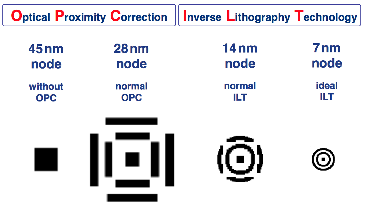
What Happened To Inverse Lithography?
What Happened To Inverse Lithography? Technology resurges as industry pushes to 7nm and 5nm.

Mask ... printed pattern on wafer.
Generating the mask is called "computational lithography"
Kind of looks like an old video game. Time to break out the Atari and design the next Apple! (with apologies to Seymour Cray)

Similar threads
- Replies
- 5
- Views
- 335
- Replies
- 55
- Views
- 2K
- Replies
- 20
- Views
- 979