diy solar

diy solar

The Magnus Effect

What about an upright spinning cylinder that can alter its shape somehow? Maybe not large scale surface deviations but like a ring of vertical aero foils running the length of the cylinder.
Fun thoughts. Economically I suspect it would make more sense to just optimize it for the most common winds at the deployment site.

I've seen airfoils added to cylinders for flight stability (like the cyclocopter above), but as the rotor has a higher lift to drag then an airfoil not sure it can add power, guess it depends on net power.... unlike a propeller that just has two energy components at right angles (lift and drag), a rotating cylinder has three (Lift, drag, spin).
 
ok, ok, how about this..

warning: disturbingly bad birds eye view diagram below1614776576478.jpeg
Carve out notches along the entire vertical length (eg subtract a smaller radius cylinder of same height)
Fill that space with something and put it on rotating axis. (yellow)

Move all to the neutral position for standby state
Move them to rotated state and now the macro cylinder will preferentially catch wind in one direction?

It’s late and i think this could be worded better.
By the way I was lazy and didn’t draw the third notch.
 
ok, ok, how about this..
I have no idea how effective it would be. I did see something vaguely similar in the literature leading to CL/CD as high as 14 on a traditional airfoil:
Mokhtarian et al. [107] investigated the effect of the leading edge geometry. One of the experimental tests was
performed with a scooped cylinder given in Fig. 51. The conclusion is that effectiveness of the leading-edge
cylinder can be improved at lower speeds of rotation by using a scooped configuration.
1614849555150.png
Possibly they were looking for the Barkly Phenomena to reduce drag on the leading edge of an airfoil.
 
i see. thank you for your thoughts.
I do like what you did, for something like a rotor propeller (e.g., replacing an airplane prop) changing the geometry might be key.

Ran across this (ref) regarding problems... it's mostly about ship propulsion rather than wind generation, but I suspect this part is universal...

Issues With The Flettner Rotor System

Unfortunately, Flettner rotors are not known for their efficiency, as it suffers from many types of transmission losses. A transmission loss is when total generated power is reduced due to dynamic issues that exist between where the source of propulsion is produced, and the actual propelling mechanisms.

In conventional systems, transmission losses are in the shaft vibrations and resistance faced by the propeller blades. To overcome these, streamlined blade shapes and dynamically isolated shafts are used (dynamic isolation refers to removing any connections between the shaft and surrounding media to prevent loss of energy).
 
This 2020 Finish paper is very interesting, their conclusion:

The results obtained in this research show the high efficiency of this type of wind turbines, which, in contrast to traditional turbines, can operate in low wind, as well as in the entire range of wind speeds have values of efficiency more than 2 times higher than traditional ones.
In their experiments the consumed power was constant, to me that suggests the mechanical drag was greater then air drag on the rotating cylinder. Here's a copy of the table and the forces acting on their test equipment. Their prototype looked to use smooth cylinders, so reducing mechanical drag, switching to a cone, using endcaps to reduce edge vortices (or more likely a ring), and/or altering the surface roughness might optimize it for low wind speed. The prototype looks very rigid, probably to reduce the vibrational losses mentioned earlier.

1615219654341.png1615219793576.png
 
Last edited:
Conical blades?

Back in post two I speculated conical blades as shown to the right. That was because the math shows
power is a square of the radius, so using that area outwards from the hub makes sense.

But is the magnus force perpendicular to the surface, or the spin?
CgjXZmpZolrUXHpurjSi.png

I suspect what will happen is the highest air pressure delta would occur at the outside ends, and push perpendicular (as with a cylinder) AND also downwards, that is a conical section would produce a force somewhere in-between. The overall gain from the diameter increase might be well worth the loss of inward force.
It also doesn't have to be conical, it could be in stages of varying diameters as shown to the right.

The problem with that is for each section to have the optimized angular velocity for windspeed, it would
need to have an independent RPM (same as the cone). But, the gains from a section spinning to fast or
slow might be moot.
1615298136201.png

Someone has probably done a paper on this. But my initial searches around terms like magnus effect and conical section turn up many hits - mainly for missile technology with air streams coming in parallel to the conical shape rather than perpendicularly. There are papers on a sphere, mainly for sports (e.g., spin on a baseball), so possibly something useful in one of those.
 
This study tested a variety of 1 meter long rotor shapes:
1615299781938.png
Blade 1 - .5m diameter, b = length-to-diameter = 9
Blade 2 - .4m diamter, b = 11.3
Blade 3 - .32 m diameter, b = 14.1
Blade 4 - .32, .4, .5m diameters,
Blade 5 - .32 m to .5m, wavelenght of 1 m
Blade 6 - .32 m to .5m, wavelenght of .5 m

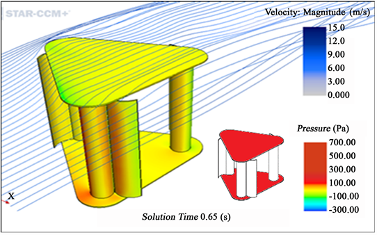
Jackpot! This study recognizes that the net power is what's important. They were also kind enough to post the energy consumption of the rational energy for blade 3. Unsure, but again looks like the energy required was independent of shape.

1615299872349.png1615300674009.png

As predicted in the post above, blade 4 (a conical frustum) produced the highest power.

In regards to starting torque:
Although the starting torque of the turbine with blade 4 is initially low and very close to that of the turbine with blade 3, the torque of the turbine with blade 4 can remain relatively high compared to that of the turbine with other blades at high tip speed ratios.

Conclusions
  • For the Magnus turbine equipped with straight circular cylinders, it was apparent that the power coefficient Cp of the turbine is highly dependent on the length-to-diameter ratio b of the cylinder. At a fixed cylinder rotation rate α, larger b results in a wider operating range of tip speed ratios λ and higher Cp. At the same λ, the turbine with cylinder having larger b can also achieve higher Cpmax at high α, in spite of the fact that its Cp can be relatively low at small α.
  • When operating at low α and λ, the Magnus turbine whose blades have a shape as the frustum of a cone has a lower Cp compared to that of the turbine with circular cylinder. However, its maximum efficiency Cpmax can be markedly promoted if the turbine and the conical frustum run at relatively high values of λ and α.
  • According to the three-dimensional numerical simulation of the flow past a wavy cylinder, the mean lift coefficient of a wavy cylinder can only reach a value close to that of a straight cylinder if the rotation speed of the wavy cylinder is twice as fast as that of the straight cylinder. In order to enable the Magnus turbine using wavy cylinder to generate a high torque, the wavy cylinder has to be rotated at a rather fast speed, which will accordingly consume a lot of energy and result in a low Cp of the Magnus turbine.
  • Controlling the rotational speed of the cylinder can be an effective method for regulating the power produced and axial thrust of a Magnus wind turbine.
α Cylinder rotation rate
b Length-to-diameter ratio of the cylinder
λ Tip speed ratio of the Magnus turbine

What's the deal with high tip speed?
I don't get it...torque is important. If anything the tip speed should be as minimal as possible to decrease drag. Shouldn't the highest force be when it's not moving at all? This doesn't make sense to me, chances are good I've got something wrong. Could this be more of an artifact of how the measurements were made?

λ = R Ω1 / Ω, where R is the radius of the turbine, Ω1 is the rotational speed of the tip of the blade, and Ω is the wind velocity
α = r Ω2 / Ω, where r is the radius of the cylinder and Ω2 is the angular speed

They're seeing best power at a tip speed of ~1.75 for blade 4. You can see in the energy plot it says the turbine speed is 90 RPM, seems too fast to me.

Update: What the Heck?

Realized Blade 1 was the same diameter as the tip of blade 4, so via the math blade 1 should have had the highest power. Possibly this is the impact from the vortices as these don't have end-plates?
 
Last edited:
Found a paper that study conical sections, but haven't found one that contains the full text for free yet.
Based on the q in the diagram (see far right image), looks like the force is a vector combined from the
perpendicular and the air flow -- chalk one up for rational thinking. ;)
Update: Well phooey... this paper was bust.
Also found another paper that studied rotor caps for VAWTS, the thinking was if
rotor caps improve the Magnus Effect, perhaps it can be applied to VAWTs?
Their conclusion was that a top cap covering all of the blades did increase
the performance, so a "ring plate" (see #27) around the rotors or a Magnus
effect generator should probably also work.
6-2320512x17.png
Conical Section rotors

11488_2020_7152_Fig1_HTML.gif

Update: SciHub, where have you been all my life? Thanks @BiduleOhm
 
Last edited:

Is it worth it to build a 5 MPH windspeed prototype?​

Design:
Wind: 5 mph (2.2 m/s)​
Optimum α with a conical frustum (Cylinder rotation rate): 3.5 (ref #28)​
Power consumed to rotate 2x blades: 72 W (ref #26)​
Optimum λ Tip speed ratio: 1.75 ((ref #28)​
4x 1 meter long conical frustum blades at .32, .4, .5m diameters (ref #28)​
Cp: 30% (ref #28)​
ρ: 1.1839 at 78°F and sea level​
Where:
A Swept area of rotor (m2 )​
Cp Rotor power coefficient​
UWind speed (m/s)
W Energy required to rotate the cylinder (W)
ρ Density of air
P Output power (W)
Unknowns:
Best width to length​
If a Ring Cap will be effective as cylinder caps​
How to minimize vibrational losses to maximize power​
Net Power generated​
Math:
Cp = (P - W) / .5 ρ U^3 A​
0.3 = (P - 72) / (.5 1.1839 2.2^3 πr^2 = (P - 72) / (.5 1.1839 2.2^3 πr^2 = (P - 72) / 19 ==> 5.9 = P - 72​
Conclusion: Nope. A two blade system would net 6W, and 4 blades 12 W. With mechanical losses, the net power would be negative.
 

Will a hurricane-proof 15 MPH windspeed Magnus compete against an Air-X?​

Design:
Wind: 15 mph (6.7 m/s)​
Optimum α with a conical frustum (Cylinder rotation rate): 3.5 (ref #28)​
Power consumed to rotate 2x blades: 72 W (ref #26)​
Optimum λ Tip speed ratio: 1.75 ((ref #28)​
4x 1 meter long conical frustum blades at .32, .4, .5m diameters (ref #28)​
Cp: 30% (ref #28)​
ρ: 1.1839 at 78°F and sea level​
Where:
A Swept area of rotor (m2 )​
Cp Rotor power coefficient​
UWind speed (m/s)
W Energy required to rotate the cylinder (W)
ρ Density of air
P Output power (W)
Unknowns:
Best width to length​
If a Ring Cap will be effective as cylinder caps​
How to minimize vibrational losses to maximize power​
Net Power generated​
Math:
Cp = (P - W) / .5 ρ U^3 A​
0.3 = (P - 72) / (.5 1.1839 6.7^3 πr^2 = (P - 72) / (.5 1.1839 6.7^3 πr^2 = (P - 72) / 560 ==> 167.8 = P - 72​
Conclusion: At 15 mph a 3blade Air-X produces about 70 W. Assuming 80% efficiency then the magnus should generate ~130W for two blades. Note that the AirX has a 46" blade diameter and the magnus calculations were 2m diameter, an Air-X with a larger rotor area would produce more power.
 
Last edited:
If the goal was to cause enough lift to evaporate water / mist - and it off set "most" of the power required, that could still be interesting.

Thank you for the research and digging through the papers.


Salter, Sortino, and Latham (2008) have proposed the use of rotor ships to propel a fleet of
1500 ships for the purpose of spraying a fine mist of seawater spray worldwide to alter the
Earth’s albedo and as a result affect the energy balance due to insolation and radiation to
space. The concept is to offset the effects of the presumed 3.7 W/m2 heating rise
apportioned to worldwide industrial activity. A concept design for a spray vessel
is shown in Figure 6.41. For the vessel shown, the wind would be blowing from
the right-hand side of the image, the rotor angular velocity would be clockwise
as viewed from above, and the resulting rotor thrust would be to the left.
View attachment 38973

Energy is needed to make the spray. The proposed scheme will draw all the energy from the wind. Numbers of remotely controlled spray vessels will sail back and forth, perpendicular to the local prevailing wind. The motion through the water will drive underwater ‘propellers’ acting in reverse as turbines to generate electrical energy needed for spray production.

I had sort of a similar idea at one point but for a different reason.

In areas such as the SW US, NW AUS, and off of S Africa (and others ) there sometimes just is not enough evaporation of sea water to produce rain that year.

In perhaps alcohol fueled theory, one could have vessels off shore spraying water mist into the air. Perhaps 50% of the droplet would evaporate to become fresh water and the other 50% would fall back to the ocean.

Hopefully some of it would form a fresh water fog / mist high enough to go over local hills and reach further inland vs normal fog.

I had thought about using more conventional wind turbine concepts to power it as the height of the spray would need to be at least as high as any modern wind turbine.
 
All I know is that in the airplane world, a cylinder is to be avoided like the plague! Fairing cub style gear, which uses round tubing, yields several mph gains in speed. Some pilots say their unfaired gear "doesn't matter" enough to bother fairing it, I tell them about the test I did years ago: holding a 4' long 1" tube out a car window at just 60 mph, it about tore my arm off. With a fairing slipped on the aft side, with the same frontal section, the difference was dramatic, and I realized the physical force I had just felt in my elbow joint was the same exact amount of force dragging the plane down if I left 4' of 1" tube unfaired! More, as it flies a bit faster than 60 mph, 85 mostly. Money drives most design though, if this worked so well on a freighter, how come we don't see them all over would be my question. Very interesting thread, thanks for sharing.
 
Back
Top