diy solar

diy solar

The "Meg" Build

Completely understand the price issue and happy to pay "made in America by someone who cares" prices :cool:
Yeah just shoot me a message with lengths and quantities and I can usually get it cut out in a day or two and throw it in a flat rate box.
Lt Dan, if I recall correctly, did you make your bus bars for EVE 280Ah cells?
Yes. Well, mine are CATL, but same thing practically.
 
  • Like
Reactions: Mia
Yeah just shoot me a message with lengths and quantities and I can usually get it cut out in a day or two and throw it in a flat rate box.

Yes. Well, mine are CATL, but same thing practically.
Right, and I just went back to re-read your post and you want to line them up end-to-end. I will cut some insulators for between the cells and measure post-to-post for my . I love the elongated holes you cut, too. Thanks man, you rock.
 
  • Like
Reactions: Mia
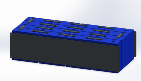
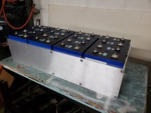
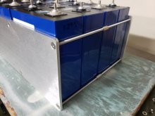
Here is a sneak peak of my battery design. The box that I'm making I havent decided on a design yet, as I have several options. But you can see my layout. I have a little more than 3/8" between the cells length-wise for my threaded rods, as I will be doing a fixture just with no springs. And I also have 1/16" plastic sheets in between each cell width-wise just to prevent any rub-through.

16s Battery.png
 
That's awesome! Looks professional

That's what happens when you've got what sounds and looks like a full fab shop at your disposal.
 
  • Like
Reactions: Mia

Looks fantastic! You could make a nice side hustle off selling those end plates in 1 cell, 2 cell, 3 cell, and 4 cell widths. I am really surprised people are not doing this as many willing to pay as we just don't have the setup to work with metal ourselves. This is a million times better than the plywood end plates we're all using.

Really nice work!
 
That's awesome! Looks professional

That's what happens when you've got what sounds and looks like a full fab shop at your disposal.
Thanks! I am pretty well equipped, but still growing my equipment. I have a larger background in offroad fab, making chassis, suspension, etc from scratch. This stuff is different but extremely interesting. I'm also really interested in making an offroad EV after I finish this project... we'll see.
I hope you don't have to lift it more than once.
Fingers crossed! I did the math, and with the box,compression plate, wiring etc, it will weigh well over 200lbs!! I'm really worried about getting it into the location I have planned out for it, as its a very tight fit.
Looks fantastic! You could make a nice side hustle off selling those end plates in 1 cell, 2 cell, 3 cell, and 4 cell widths. I am really surprised people are not doing this as many willing to pay as we just don't have the setup to work with metal ourselves. This is a million times better than the plywood end plates we're all using.

Really nice work!
I would be open to that as well. Mine is made of 1/4" Aluminum and you can still see the cells kind of flexing the 1/4". I can't imagine how much even 3/4" plywood moves.
 
  • Like
Reactions: Mia
I hope you don't have to lift it more than once.

Fingers crossed! I did the math, and with the box,compression plate, wiring etc, it will weigh well over 200lbs!! I'm really worried about getting it into the location I have planned out for it, as its a very tight fit.

... as I will be doing a fixture just with no springs.

Keep in mind that depending on SoC, there may not be enough compression to lift the weight.
I they do try to slip out, and busbars are installed, maybe that'll save the day when they catch on the rods? ?
Consider a way to support the cells from the bottom. I'm thinking a sheetmetal piece that loops over the bottom rods and tucks under each cell (with abrasion protection as needed.)
Or just straps under all the cells as a lifting fixture. Plastic banding around each group of 4?
 
Progress...
I don't know what you torqued the screws that clamp the plates. Be aware too much compression is worse than no compression.

I suggest installing some insulating material between the plates and the cells, and between each cell. If you take your meter and measure the voltage between the QR code and the negative terminal of the cell you will get a voltage reading. The current is very small. However it's possible the PVC wrap of the cells will wear through over time causing the cells aluminum cases to contact each other and this could cause problems over time.


Also did you install tubing over the threaded rods? And is the coupler between the rods making contact with the cell?
 
my thoughts....

1. you need micro-air soft starts on all 3 AC to reduce the start up current from 70a to like 12a or so... be much easier on the inverter (at least on the one you plan to use the most.. i don't see you running all 3 on solar)

2. plastic tubbing around your all thread

3. in my build i used 3m VHB tape between my cells. 3 vertical stripes. for insulation also locks them together very very well. you can lift the 8 I have before compression as one unit
 
Keep in mind that depending on SoC, there may not be enough compression to lift the weight.
I they do try to slip out, and busbars are installed, maybe that'll save the day when they catch on the rods? ?
Consider a way to support the cells from the bottom. I'm thinking a sheetmetal piece that loops over the bottom rods and tucks under each cell (with abrasion protection as needed.)
Or just straps under all the cells as a lifting fixture. Plastic banding around each group of 4?
Yes, I plan to make an actual aluminum battery box, that will house these batteries, the BMS, etc, so I will not be lifting by the fixture.
I don't know what you torqued the screws that clamp the plates. Be aware too much compression is worse than no compression.

I suggest installing some insulating material between the plates and the cells, and between each cell. If you take your meter and measure the voltage between the QR code and the negative terminal of the cell you will get a voltage reading. The current is very small. However it's possible the PVC wrap of the cells will wear through over time causing the cells aluminum cases to contact each other and this could cause problems over time.


Also did you install tubing over the threaded rods? And is the coupler between the rods making contact with the cell?
I have no way of measuring the torque on them, but I think I'm going to discharge the batteries all the way, then just "snug" the bolts to the point where it all stays in place, but no pressure on it. Then as it charges, it will apply more pressure.

There is .060" sheets of HDPE for insulation in between each cell.

I do plan on getting some thin tubing and covering all the rods, I just haven't done it yet. I'm also not so happy with how the union nuts work, and I am debating on changing it up, as it is a real chore to get that all put together.

my thoughts....

1. you need micro-air soft starts on all 3 AC to reduce the start up current from 70a to like 12a or so... be much easier on the inverter (at least on the one you plan to use the most.. i don't see you running all 3 on solar)

2. plastic tubbing around your all thread

3. in my build i used 3m VHB tape between my cells. 3 vertical stripes. for insulation also locks them together very very well. you can lift the 8 I have before compression as one unit
Thanks for the info, I do plan on doing AC mods in the future, its a shame the soft starts are so damn expensive or I would do them all right away.

2 and 3 ive already addressed above.

Thanks everyone!!!!
 
I would be open to that as well. Mine is made of 1/4" Aluminum and you can still see the cells kind of flexing the 1/4". I can't imagine how much even 3/4" plywood moves.

My 280Ah cells in a 4S configuration have 3/4" Poplar plywood frames. There is no flex. But, if I built something with a lot of cells like you did, I wouldn't be using plywood either.
 
Thanks for the info, I do plan on doing AC mods in the future, its a shame the soft starts are so damn expensive or I would do them all right away.

2 and 3 ive already addressed above.

Thanks everyone!!!!

My Imagine trailer on has 1 A/C on it and I put a Microair soft starter on it a couple of years ago. I love it! I ran it from my inverter for the first time yesterday and no issues at all. It's your run-of-the-mill inefficient camper A/C unit that draws about 1050 watts when running (didn't measure the inrush current yet). They are pricey, and putting them on all 3 A/C units would be expensive. But you'll appreciate having them when you do it.

I can run my A/C directly off a Honda EU2000i w/o stalling the generator, even on ECO mode.
 
I've been running all 3 through the inverter in just bypass mode with no worries so far, especially when I need to cool the trailer quickly after we've been gone for a while. I brought the 98* inside temps down to 75* in about an hour yesterday.

In addition to the soft starts, I would love to add THESE as well. They seems to greatly improve AC efficiency, which in turn means the AC runs less, less stress, less wear and tear, and less power used! But $170 and I need to buy 3 of them! Jeez...
 
In addition to the soft starts, I would love to add THESE as well. They seems to greatly improve AC efficiency, which in turn means the AC runs less, less stress, less wear and tear, and less power used! But $170 and I need to buy 3 of them! Jeez...

I've seen several YouTube videos where people describe making their own baffles out of foam insulation board and aluminum tape. Much cheaper, but more time consuming.
 
Yesterday I was in the trailer making food for the kids while they were watching TV. I happened to have all 3 ACs on, all the lights, 50" Smart TV and I started the microwave ?

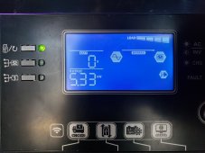
And it did it flawlessly! After about 15 seconds of the microwave going, I realized it and ran out to see if the inverter was on fire or not, and it was only at 5330 watts! The fan were slowly ramping up to full speed it sounds like, but it took it like a champ.

20210419_180815.jpg
 
And it did it flawlessly! After about 15 seconds of the microwave going, I realized it and ran out to see if the inverter was on fire or not, and it was only at 5330 watts! The fan were slowly ramping up to full speed it sounds like, but it took it like a champ.

Thanks for that! I went back through the thread to discover your model = LV6548. Sounds like something from ALIEN :D

I'm interested in a 48v setup, no need for 220 on my rig just the 110. I'm going to explore that product line thanks to your post.

You've made some amazing progress in record time, very impressive implementation.
 
Yesterday I was in the trailer making food for the kids while they were watching TV. I happened to have all 3 ACs on, all the lights, 50" Smart TV and I started the microwave ?

And it did it flawlessly! After about 15 seconds of the microwave going, I realized it and ran out to see if the inverter was on fire or not, and it was only at 5330 watts! The fan were slowly ramping up to full speed it sounds like, but it took it like a champ.

View attachment 45899
I believe in bypass mode your inverter isn't doing anything... just a closed contact on a relay.. so you can't really overload it......
 
I believe in bypass mode your inverter isn't doing anything... just a closed contact on a relay.. so you can't really overload it......
Even if it is a closed contact relay, 5300 watts is still well within its parameters. Im thinking theoretically it will not overload it.

As a side note, I was reading through the manual and saw it will support 2x max load for 5 seconds. Thats 13kw for 5 seconds? Nice.
 
Back
Top