diy solar

diy solar

The "Meg" Build

If it were a house, wires to panel frames or other UL listed system would be required.
If a metal skinned RV, you may already have some electrical connection. If not, they're isolated and you wouldn't come in contact unless on the roof.
Most people don't do anything about it on an RV. Older systems were "12V" so about 25 Voc.

Will started out demonstrating things that worked for van/RV, later showed household wiring using non-NEC approved techniques which some people jumped on.

Your unique situation is higher voltage remote array, which might bias trailer with DC in event of a fault. Maybe AC in your case, we're not sure.
 
Ok, I'll order a 500ft spool of 18ga or something to run along with the PV Wires.

That will take care of AC voltage if present.
I think AC voltage measurement from RV chassis to PV positive & negative will show if there is anything to fix or not (in which case that wire doesn't help.)

If you did later get a short from PV positive to container, and if there is a solid connection from PV negative to RV chassis, the 18 awg wire would burn out.

Some PV connections have a 1A "ground fault" fuse between PV negative and ground. If there is a short, fuse blows and system detects voltage, shuts off. My GT PV inverters have that. Midnight SCC with GFCI may have similar function. I don't know if yours does, or how PV connects to RV chassis. I would expect PV negative to go to battery negative and probably chassis.

My remote ground mounts have 12 awg in conduit for PV and 12 awg ground, for 600V (max) PV strings.
So to be on the safe size, I should match Ground wire with PV wire size, but is that also with each string, meaning I have 2x strings of 10ga PV wire, I would need 2x 10ga ground wires?
 
Technically. Or a single conductor with suitable ampacity.
Requirement is probably reduced if limited by breaker or GFCI.
Practically speaking, a single short would only have current from one string, but two shorted could theoretically happen.
To pass inspection an installation should meet the letter of NEC. Inspectors might not observe all details. I would expect drawings to be checked before permits issued, and inspector to compare installation with drawing. In practice, they probably look for obvious mistakes and their pet peeves, dig deeper if they find things wrong.

What is Isc of each string?
Ampacity of current carrying conductors is supposed to be Isc x 1.56 for PV systems (x2 if carrying current from 2 strings.) That's the usual 1.25x for margin, and another 1.25x for extra illumination.
Isc x 1.56 would also be minimum size for fuse/breaker to avoid nuisance trips.

Ground wires are often smaller than current-carrying conductors because won't see continuous operation, breaker trips. For PV with no breaker, will be continuous operation. Not sure, but maybe supposed to be as large as current carrying conductors (not sized by PV) if no OCP; array could be changed in the future.
 
I'll get that ground wire situated asap.

My next little project is, I wanted to install a Nema 14-50R plug in the compartment with the inverters, as well as a Nema L9-30R and some standard 15-20a plugs. So I'm thinking I kill 2 birds with one stone and install a main Breaker Panel, with the outputs of the inverters going to this main breaker panel, then add breakers going to these various plugs in the compartment, with a 60a Dual pole breaker going to the trailers factory distribution panel (sub Panel).

I'm hoping by installing a main breaker panel, I can some how have the neutral/ground bond automatically when not plugged into the grid. Is there a way to do this?
 
I'm hoping by installing a main breaker panel, I can some how have the neutral/ground bond automatically when not plugged into the grid. Is there a way to do this?

Buy a Victron inverter :cool: Sorry, I couldn't help myself.
 
I figure one can install a "dead" outlet with neutral wired to ground. Park your shore power plug in that outlet when not in a shore pedestal.
Not quite automatic, but provides a ground bond. So long as neutral isn't isolated by relay.
 
I figure one can install a "dead" outlet with neutral wired to ground. Park your shore power plug in that outlet when not in a shore pedestal.
Not quite automatic, but provides a ground bond. So long as neutral isn't isolated by relay.
Thats a good idea. Can I have a relay get energized by one of the input legs from the grid to break the bond of the inverters neutral/ground output?
 
I suppose the mobile inverters use a relay to do it that way.
Apparently shore pedestals are available with all sorts of miswiring, so testing them before use and having cords to swap miswiring is common.
If shore power goes down while plugged in, your ground bond relay would get connected in parallel with shore pedestal's bonded ground, but I think that doesn't actually cause any harm.

My idea of of the dead outlet was manual switching, no relay. You just transfer the plug.
 
What happens if a sub panel also has the neutral/ground bonded, in addition to the main panel being bonded?
 
What happens if a sub panel also has the neutral/ground bonded, in addition to the main panel being bonded?

If Current flows through the hot "Line" and is supposed to return in the "Neutral", it could split into "Ground".
That might exceed current rating of ground wire and overheat it.

Perhaps with multiple faults, it could cause ground of appliances to become hot.
For instance, if utility supplies 120V to "Line", and both "Neutral" and "Ground conductor are open circuit (but neutral and ground bonded at the RV). In that case RV chassis becomes 120V.

In the situation where no current flows through "Line" to shore power pedestal, I don't think there are any negative consequences to you having ground and neutral bonded both at RV and at utility source.

This one should do the trick right? Its a 2 pole contactor, but its normally closed, so it should be just what I need?

I think so.
 
Alright, trailer goes into hardware mode this weekend. Gonna go pickup a breaker panel, some breakers, 4/4 SOOW cable, and some NEMA plugs and get started.
 
Whoa. Interesting. I just got this email back from Andy at MPP Solar

Hi Daniel

Due to the original design of this unit, when this unit works in battery mode, the N-G terminal of AC output will be short. When this unit works in the line mode, the N-G terminal will be open. Thank you.
Best regards,
Andy Y. ¦ Support Team, MPP Solar Inc.
support@mppsolar.com ¦ www.mppsolar.com

So I guess the NG Bond I've been worrying about is irrelevant?
 
Whoa. Interesting. I just got this email back from Andy at MPP Solar
Not relevant to your situation but if I understand Andy correctly the mpp units should be fine for mobile applications with intermittent access to shore power.
This is good news.
 
Whoa. Interesting. I just got this email back from Andy at MPP Solar


So I guess the NG Bond I've been worrying about is irrelevant?

So that means your inverter has automatic bonding.
That makes the idea of adding a relay or socket for bonding irrelevant.

"Trust but Verify" - measure with a meter.

Wonder if something about this also causes your RV chassis to become hot. A path/coupling from AC Line out to earth would do that.
The PV wires to shipping container are what I was curious about, if any AC voltage is superimposed on them (relative to chassis), because they may have some capacitance to earth.
 
Not relevant to your situation but if I understand Andy correctly the mpp units should be fine for mobile applications with intermittent access to shore power.
This is good news.
It sounds like it!
So that means your inverter has automatic bonding.
That makes the idea of adding a relay or socket for bonding irrelevant.

"Trust but Verify" - measure with a meter.

Wonder if something about this also causes your RV chassis to become hot. A path/coupling from AC Line out to earth would do that.
The PV wires to shipping container are what I was curious about, if any AC voltage is superimposed on them (relative to chassis), because they may have some capacitance to earth.
How can I verify with a meter? Everyone has told me checking continuity is not good enough for verification.

On another note. How do we know the earth doesn't have stray voltage from something else?
 
If you connect a light bulb or other significant load like space heater or hair dryer from Line to Ground, it should get power. Even then, voltage from Neutral to Ground should be zero.
Load from Neutral to Ground should not get power.

I think grounding test of equipment, from ground wire to chassis, is done at 10A or so and voltage measurement to confirm a small fraction of an ohm.

On another note. How do we know the earth doesn't have stray voltage from something else?

Could be ...
If Earth has voltage, it has the same voltage everywhere and won't affect you (unless a current is running through it, like from a downed power line.)
You apparently have RV chassis driven to an AC voltage relative to earth. But AC voltage across that distance of earth could also do it.

If you get that length of phone wire, connect one end to shipping container and unroll it over near RV. Use your meter to measure from other end of wire to earth. If you see voltage, current could be flowing through the earth. If low, that's not the problem.
Measure voltage from wire to RV. If that has voltage (with PV wires connected to container), then I'm back to thinking your system drives voltage into those wires.


(That's why I jokingly told you to jump from RV to ground with both feet, and shuffle forward in small steps without picking up your feet.)
 
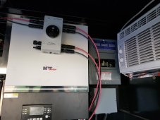
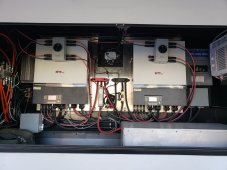
Started installing the breaker panel,. I removed the knockouts I was going to use, installed a 60a breaker to go to the trailers distribution box, and a 20a breaker to run my GPU Miner on 240v. I also need to get a 50a 2 pole breaker to wire up a 50a plug for my welder/other equipment, but the electrical supply place was sold out of the 50a breakers and 4/4 SOOW wire. I await till Monday...

Its getting to be a little cramped in here!!
20211120_144523.jpg

20211120_144529.jpg
 
Back
Top