diy solar

diy solar

The rack mounted Quattro 10,000VA

HighTechLab

AKA Dexter - CTO of Current Connected, LLC
Joined
Sep 23, 2019
Messages
1,688
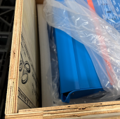
One of my inbound Quattro 10K shipments from Victron came in with the case severely damaged...I have been asking so many suppliers to make a good rack mounted inverter/charger with no luck...so now it's time to make one on my own!

I have a 6U prototyping server rack case on the way...my goal? Move all the guts into this case. Perhaps Victron will be inspired by the project and make a product like this. It would be a great addition to all of these rack mounted battery builds.

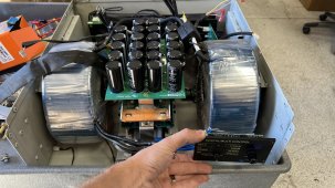
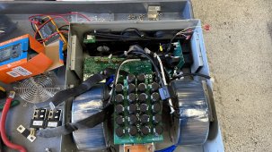
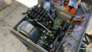
This thread is a progress log of this project. So far I've taken the whole unit apart. Here is what the guts look like:
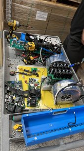
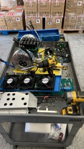
IMG_0980.JPGIMG_0981.JPG
 
Nice!
That doesn't quite seem like 6U worth of stuff if you can lay down the 2 coils and capacitor board. But, I'd start with the biggest box and let Victron slim it down when you convince them.

Got pics of the damage? How bad was it?
 
Heat and convection need to be designed correctly.

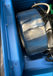
The toroids get hot when under load for some time, having a good forced air flow over them is a must.

Normally i design big power inverters, 6Kw and upwards, with a push pull forced temp control fan system.

Fans draw in air from the base of the machine/case and push air up the case and exit at the top of the machine.

In low use conditions with no fans then the machine naturally does this convection process.

Allways amaze folk how good cooling can inprove an Inverters output significantly.

Toroids, capacitors and the Power electronics need cooling properly.
 
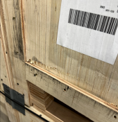
The damage essentially was the top lid. The crates these come in are stacked 3x high. My suspicion is that it was tipped over and this was the unit on top.

1666615768956.png
1666615795896.png
1666616040504.png


lay down the 2 coils and capacitor board
I was thinking this at first, but the problem with laying down the fet/cap board would be the airflow would be perpendicular to the heatsinks, rather than in this standing orientation where it would be parallel.


having a good forced air flow over them is a must.
I'm planning to reuse the 3x ~120mm fans that the unit originally had. Just like a server, pull cold air from the front of the rack and push it out the back across the tx's and fet board first.

Not that it's a way to skimp on proper cooling, but the nice thing is that there is thermistors inside of each transformer and in multiple places on the fet board.
 
I'm feeling really good about everything fitting.
I'm thinking of designing the case so the AC power can exit from the rear, with DC and control at the front. It would be a cluster trying to fit DC, AC AND airflow on the front panel.

I opted to put the FET board and transformers at the front for the simple reason of reduced length main DC run (probably just going to use a bus bar). The plan is to have the fans at the back push air out of the case, then the front panel can be louvered as needed to get air to enter precisely where its needed.

9523F4C4-6AD4-4EDA-8B84-7CAE2861D9C1.jpeg
8AECB864-E868-4C9C-9DF6-602ED0485E39.jpeg
8EDC3E25-F38C-4E2E-BA0C-0D179A45CF44.jpeg
 
One of my inbound Quattro 10K shipments from Victron came in with the case severely damaged...I have been asking so many suppliers to make a good rack mounted inverter/charger with no luck...so now it's time to make one on my own!

I have a 6U prototyping server rack case on the way...my goal? Move all the guts into this case. Perhaps Victron will be inspired by the project and make a product like this. It would be a great addition to all of these rack mounted battery builds.

This thread is a progress log of this project. So far I've taken the whole unit apart. Here is what the guts look like:


View attachment 117521View attachment 117522

Would be better if you just make an adapter to convert the victron to rack mount by getting some ears made I would think.
 
I assume the Quattro has permanent AC connections not outlets? It does seem quite messy to try and shove all the connections on the front.

Also, I didn't realize the scale. I had assumed the entire cart was only slightly larger than a rack. Now I see the challenge and why things are stood up vertically.
 
I would strip the plastic off the torrids, so the bare copper could enjoy full forced variable high velocity ventilation with secure mounting.
 
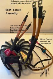
Here is one of my 38kg / 83lb, 6KW run all day, complete toroid assemblies. Note .... the toroid has centre air flow.

Primary winding is 50mm/2 cable.

6kWToroidAssemby.jpg
 
Back
Top