diy solar

diy solar

Thermocouple interference

Hedges

I See Electromagnetic Fields!
Joined
Mar 28, 2020
Messages
20,584
Anybody got advice on taking thermocouple measurements in close proximity to AC signals?
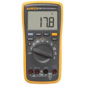
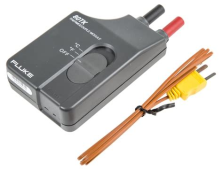
Seems I fooled myself with the "1 mV per degree" reading of my meter when thermocouple is connected through an adapter.

1651966959485.png 1651966989855.png

To debug, I tried reading DC mV of thermocouple directly. 000.0 mV
Then I tried my 6.5 digit microvolt meter.

1651967067644.png

The thermocouple produced 50 microvolts.
Pinched between my fingers, 200 microvolts.
Held against a cool piece of aluminum, went to zero and changed polarity.

OK, this is a small signal that needs amplification.

My test setup was meant to study refrigerator/freezer behavior. Three thermocouples and a current transformer fed into a DAS. The CT is 333mV for 100A, so I put 10 turns through it.

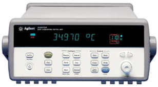
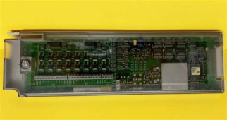
34970A DAS, 34901A 20-channel mux installed, 34907A multifunction card removed because manual says it would interfere with thermocouple (reference junction?)
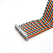
50 pin ribbon cable (flat, no twist) extends all 34901A connections out to wire-wrap breakout board.

1651967303365.png 1651967594651.png 1651967649466.png 1651967438245.png

I connected three thermocouples to last three relays, CT to first.
Parallel untwisted wires 0.050" apart, but 200 mVrms of CT is 2" away from thermocouples.

Temperatures read OK by themselves.
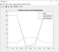
I plugged a 700W heater through a footswitch, logged several data points with it off & on.

1651967887710.png
Temperature readings went to about zero when 6A measured.

1651967809733.png

I enabled averaging of 10 power line cycles, no improvement.

to be continued ...
 
Last edited:
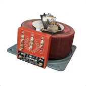
I connected a variac to reduce voltage to heater and measured current.

1651968125619.png

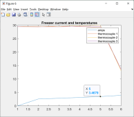
At about 3.5A registered, 115 mVrms from CT going through ribbon cable, is threshold where thermocouple readings were disturbed.

1651968173838.png


I hadn't expected 115 mV between wires 0.050" apart, 2" from other pairs of wires, length 3', to clobber my 10's of microvolts signal. Well, I hadn't comprehended how low the signal.

I tried 2 passes of thermocouple through a randomly selected ferrite (lifesaver size), no effect. (might have helped reduce common-mode, but not differential mode, reaching thermocouple itself. Hmm, need to try blocking differential mode AC.)
Suppose I could try grounded foil shield around ribbon cable.

Other suggestions from people who've been there, done that?
 
Looks like shielding and possible twisting the thermocouple pair without shorting it might help.
Your TC wire is making a nice antenna. At work they use inconel sheathed TC's with ungrounded junction to help with noise.
The other end of the sheathing (opposite the TC junction) is then grounded. (TC junction is not)

Kid
 
Also the cold junction compensation of a 34970 card is not very good. (just a thermistor)
But sufficient for relative measurements between several TC's. Can you lengthen the integration time for the 34970?
BTW, nice instrumentation for a home lab.

Kid
 
Last edited:
A logging TC/mV scanner would be helpful, but might be cost prohibitive.
A cheap one from omega with 8 channels is ~ 500 bucks.
Could you not read your TC's with the 34970 and attach your CT coil to the 3456A?
I seem to remember you can define channels on the 34970 as temperature and TC type.
Kid
 
The em field of the heater may be contributing as well to your percieved noise problem.
Also 10 power line cycles is rather short for this measurement. Try increasing to at least 50 NPLC.

Kid
 
Maybe a silly idea: what about using other kind of temp sensor with more noise immunity, like DS18B2x or NTC or....?
 
+1 on the twisting the TC wires in order to reduce the antenna coupling efficiency.

Been there done that. Worked for me years ago. YMMV. Ampere’s law is cool until when you dont need it :)
 
Maybe a silly idea: what about using other kind of temp sensor with more noise immunity, like DS18B2x or NTC or....?

I just assumed thermocouple was the standard, most appropriate temperature measurement for lab setup. The meters I've used didn't have TC input, but I got the Fluke adapter for a previous employer, dedicated one HPIB meter to reading it. Later bought a similar adapter for my own use.

Guess it's a good thing the PCB designs I did used NTC thermistors for temperature sensing of control loops. Signal is as big as my resistor divider made it. Pain for software guys who want to get an actual number out. "Calibration", not my problem; I just offered the hardware. I also used I2C devices with calibrated temperature to digital in them.

Yeah, something with big signal, mV per degree not some microvolts, would be more immune.

A logging TC/mV scanner would be helpful, but might be cost prohibitive.
A cheap one from omega with 8 channels is ~ 500 bucks.

I've seen multiple-input TC devices. I've got a bunch of GPIB equipment so using that. First thought was muxing several TC into the adapter, but realized my 34970A DAS could do that directly.

Could you not read your TC's with the 34970 and attach your CT coil to the 3456A?
I seem to remember you can define channels on the 34970 as temperature and TC type.

Yes, various mux cards for 34970A support TC. 34901A 20-channel mux can be configured for TC, NTC, other type devices. For some reason, it says not if 34907A multifunction card installed. That's why I used separate DMM before. This time I wanted multiple TC channels, so I unplugged the offending card.

Since temperature worked before CT signal was present, separate DMM would work. DAS ought to be able to log multiple channels so that would really be throwing in the towel. Bigger issue is portability and control. I want to pull DAS out of the rack, take it to where the freezer to be studied is, run it standalone.

What I wanted to do was study how ice bottles or brine bottles maintain temperature in freezer with power shut off. I figure we know H2O holds zero C, but brine I'm thinking will change temperature as concentration changes.


Also the cold junction compensation of a 34970 card is not very good. (just a thermistor)
But sufficient for relative measurements between several TC's. Can you lengthen the integration time for the 34970?

Instructions also say this particular mux provides in internal reference or an external ice water/TC reference. I figured higher accuracy was available, for tracking freezer temperature standard TC with electronic reference is good enough. Could it be just a TC on the card and we tell it we're at room temperature? That would only be as good as the room is stable. Something about electronic simulation of junction in most devices.

Integration time? I did 10 PLC, but did you mean something else?

The em field of the heater may be contributing as well to your percieved noise problem.
Also 10 power line cycles is rather short for this measurement. Try increasing to at least 50 NPLC.

Maybe for a different setup. Electric radiator with zip cord is 6' from thermocouple (not gathering data, just getting functionality in the lab.) Zip cord is plugged into foot switch (or now through Variac, but had issue without Variac as potential aggressor), extension cord to outlet. Put 10 turns of neutral around CT just before plug, and slipped Fluke current probe through so it has 1 turn.

10 PLC too small? Certainly I've done more for high accuracy, but here just trying to get readings of degrees. If signal has 60 Hz riding on it, just 1 PLC ought to mostly zero that.

I would guess the interference is railing input to amplifier circuitry. Maybe I need to put hardware LPF signal conditioning between sensor and circuitry. But this assumes interference is in my wires, not the MUX card layout (reasonable guess, card is from HP and meant for the purpose vs. I have ribbon cable extending its terminals to a convenient 50 pin header.)

+1 on the twisting the TC wires in order to reduce the antenna coupling efficiency.

Been there done that. Worked for me years ago. YMMV. Ampere’s law is cool until when you dont need it :)

Looks like shielding and possible twisting the thermocouple pair without shorting it might help.
Your TC wire is making a nice antenna. At work they use inconel sheathed TC's with ungrounded junction to help with noise.
The other end of the sheathing (opposite the TC junction) is then grounded. (TC junction is not)

Twist and shield, certainly the first thoughts.
I wasn't expecting twist to matter with 60 Hz interference, but even far below a wavelength it would balance. Weak interfering signal, but I keep forgetting how sensitive a circuit the amplifier must be.
I usually think of twist to reject high frequencies on a small scale (and powerlines from EMP).

The fluke TC I used before might have had a low twist. The TC wire spool I got for this project was untwisted.

Shielding seems the thing to do. Flat foil shield over ribbon cable for one. I got a 3' 50 wire cable with connector at one end, split to groups and singles to fit screw terminals in mux. This lets me move from one 50 pin header to another, connect DAS to various projects without opening it up and turning screws. Was fine for low-noise low-sensitivity testing. Inside the mux, more clumsy to shield the split ribbon cables.

Foil or braid over TC wires should be doable.

Hmm, where to connect shield isn't obvious. I'd want chassis ground at mux, have to see if it has one. The 50 screw terminals are all signals which I've connected.

I suppose the right way to use mux was shielded twisted pair (or two pair for kelvin) to mux channels. But not clear where to ground. A long wire grounding would be a pickup of common-mode.

Manual, under "calibration" describes wiring. But that says ground shield to calibrator output.

"Note: Use shielded twisted pair PTFE insulated cables to reduce settling
and noise errors. Connect the shield to the source LO output."


BTW, nice instrumentation for a home lab.

Kid


Yeah, thanks!
Previously I was mostly cheap, an old analog scope and the like. One good handheld Fluke because I care about measuring line voltage before working on it.

I took a job designing a "Quadrupole Atomic Mass Spectrometer" a.k.a. "Residual Gas Analyzer", such as what is found in a smog-check machine. I was to design some of the analog and RF boards. Since I was a contractor initially before they became a U.S. entity, I realized anything I bought for my lab would effectively be discounted by my income tax, FICA, self-employment FICA rates.

I've spent maybe $25k mostly on older equipment that probably had $200k MSRP. VNA, spectrum analyzer, EMI probes, DAS, ppm stable DMM, etc. (The DAS in particular was to automate board testing, and same model is part of their factory test now.) I later moved into the startup's location. When I left, took it back home (and the company lab was left with almost nothing.)

Good old stuff is much more affordable than when new, and compared to current new models of top brands. Off-brands can be an economical alternative.
When I started working at HP in the 1980's, they came out with the 8510 VNA (50 GHz). It cost 7x my annual salary :ROFLMAO:

What most VNAs, like mine, don't do is power line frequencies. One at work does do 5 Hz to 500 MHz.
I use a LCR meter 20 Hz to 100 kHz for coupled transformer/choke models. But that doesn't determine hysteresis. Maybe could do saturation by stepping DC bias.
Recently I've been using digital scope, current probe, Variac to get B-H curves. Those have been needed to predict effectiveness at suppressing lower frequency interference. Deep memory doesn't help much, but higher resolution like 12 bits does.

I'm going to try some transformer saturation and inrush measurements at home later.
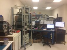

Donald's lab.jpg
 
What I meant for NPLC is (number of power line cycles). It is the integration time based on line frequency.
Since you don't require fast scanning, 50 - 100 would allow more time to for the integration of each measurement, providing a better measurement. 10 PLC is 1/6 of a second at 60 hz. I find when calibrating TC measurement instruments that the longer integration time help considerably. Also scanning with both the CT coil and the TC's hooked to the 34970a is causing the internal dmm to change ranges constantly. (I think it would anyway) Longer integration time will help settle that.

Kid
 
  • Like
Reactions: feo
Possibly ranges, but I figure 34901A has TC compensation circuitry. My plug-in DMM adapter puts out one mV/degree. if same for 34901A, would be 23 mV. The CT was reading about 200 mV.

Given that the temperature reading was clobbered from 23 degrees to zero degrees or less, didn't seem to be just a bit of random movement, I think the noise is saturating/railing compensation circuitry. Not something more power line cycles of averaging will help with.

I have seen where AC coupled RF railing an op-amp circuit still let it almost work. Instead of linear output it looked more like PWM, and LPF cleaned it up well enough the machine was operated that way for years. Kind of non-linear, though, till we found and fixed it.

34970A manual does say to put like signals on adjacent channels to minimize wear-out of DMM relays from range switching. I have CT on channel #1, TC on #18, #19, #20. If it was error due to not settled, the 3rd TC read would be better, but it isn't.

I have used many PLC on 3456A trying to squeeze out more digits accuracy. That was after company returned the 8.5 digit 3458A they had rented for one month. I did similar but averaging many RF cycles and multiple traces to get more like 14+ bits out of an 8 bit scope (to calibrate linearity of a circuit.)

I do have 34905A dual 4-1 RF mux (BNC). Maybe I should connect my TC channels through that, feed to DMM TC adapter, then read the voltage output. That will keep low-level signals in coax and in a different module. That's cheating but should make this project work. I ought to be able to use the mux that supports many temperature sensors.

1652034896155.png
 
34970A manual does say to put like signals on adjacent channels to minimize wear-out of DMM relays from range switching. I have CT on channel #1, TC on #18, #19, #20. If it was error due to not settled, the 3rd TC read would be better, but it isn't.

I think I have experienced very weak signals being slow to drive a bus. I was programming an SMU and mux to test an analog ASIC (for HoloLens), and wanted to be extremely careful about voltage and current driven to not damage first sample ICs. I think I set current limit to 0.1 mA, within safe limits for IC inputs. That seemed to result in large measurement errors. One channel with higher loads required me to increase current drive and behaved much better. I didn't get to spend more time after the first 2 weeks debug and bringup so never had a chance to see if just raising current limits on SMU for the other channels tested would have resolved the issues.
 
My test setup was meant to study refrigerator/freezer behavior. Three thermocouples and a current transformer fed into a DAS. The CT is 333mV for 100A, so I put 10 turns through it.

At about 3.5A registered, 115 mVrms from CT going through ribbon cable, is threshold where thermocouple readings were disturbed.


head-bang-emoji.gif


All I have to do to get it working for single-digit amperage loads is not do 10 turns through CT.
(I'm good at kicking the can down the road. Maybe I'll come up with an engineered solution that allows full range later.)
 
Depends what you want to use all this for I suppose.
Thermocouple wire is used in industry because its cheap and accurate for temperature measurement if you want to monitor a very large number of temperature channels, although the logger required to do it properly will likely be horribly expensive.

For a home project there are far better and more suitable and convenient sensors available such as the LM34 and LM35 temperature sensors. These give a direct millivolt output reading in either Fahrenheit or Celsius without any calibration or scaling. These are also far less susceptible to electrical interference. For most things +/- one degree untrimmed accuracy is probably quite sufficient.
https://www.ti.com/lit/ds/symlink/lm34.pdf
 
10 mV/degree F would make it easy to read with DAS.
Mine has 3 slots including a 20 channel mux card, cost about $1000. Not inexpensive, but standard test equipment.

I think this is what I used in previous board designs. I2C interface, 3 pin address so 8 can be used on one bus branch:

 
Back
Top