diy solar

diy solar

Thoughts on 12v high amp discharge battery builds

jbird526

Solar Enthusiast
Joined
Feb 16, 2021
Messages
202
Location
Maryland
As I browse the different posts about battery builds, I have seen several users building 280ah 4s packs and then trying to find Quality/Inexpensive/HighAmp BMS's able to support say a 2000 watt inverter. Quality/Inexpensive/HighAmp BMS seems like a Venn diagram. You can only pick 2.

I hesitate to use say a Daly 200 on a 280ah pack as I have not seen great consistency. Overkill seems to have good reliability and great service but for 12v only 120amp capability. Jumping to the next level of a Tiny BMS I haven't seen good results with relays. Probably not researched enough and only seen people trying to use cheap relays.

So my question/thought is would it be better to build 100ah packs with Overkill 120amp BMS and run them in parallel? At least until something is on the market with higher 12v high amp output? Parallel Overkill BMS on the same pack is not recommended so won't entertain that. If the man says not to do it, then I would suspect a warrantee issue.

This completely excludes 24 and 48 volt as that is another discussion.

Feel free to completely tear apart this post as I may just be ignorant.
 
I'm relatively new to all of this also and wrestled with installing a 12v or 24v battery system in my RV. Ultimately I went with 12v so I didn't have to bother with one or two DC-DC converters to run my existing 12v accessories/lights/pump/etc. You can use a low-power BMS in conjunction with a good high current contactor (GigaVac brand seems highly recommended). I chose to build two 4S 280Ah packs, each with their own 120A Overkill BMS. I have a single MultiPlus 12/3000/120 that will pull a max of 100A from each battery in parallel at peak current. Ultimately I plan to build two more 4S 280Ah packs after my wallet stops smoldering from all this recent spending :). If I'm wrong about the power handling capability of the Overkill BMS on the separate batteries packs in parallel, then I'll add contactors. I hope this helps.
 
I’ve gone for two of the jbd 150a versions. Each Bms on its own 4 s pack.

my inverter is 8kw / 4k continuous, however I don’t this I’ve ever needed to get it much mast 3k. at these levels the 150a Bms units don’t break a sweat. The 100 or so amps out of each unit is take. In its stride while induction cooking with the air con.

what I like about the 150a units is that I can run 70mm2 hi flex cable. The lugs l, cable etc comming off the Bms provide a huge additional heatsink . The huge surface area of the lugs also helps.

i interconnect with 350 or 175a Anderson’s for easy plug and play functionality.
 
So my question/thought is would it be better to build 100ah packs with Overkill 120amp BMS and run them in parallel?
You could do that and have roughly 240 amps throughput.
I would suggest designing for less as the current paths will have slightly different resistance and won't perfectly balance the current.

Alternatively...
In most systems the inverter draws the huge majority of the current.
So you can remote control the inverter via a solid state relay which is in turn driven by the BMS.
Then you wire the inverter to bypass the BMS on the return leg and Bo's yer uncle.
 
Guess it comes down to necessary scale and bank account at the time of conception. A single 100ah would give you an inexpensive but short AH and low AMP output battery capable of supporting a 1000 watt inverter. Paralleling 2 of those together would allow you to support a 2000 watt inverter but beyond that you have diminishing returns. Also as 280ah cells appear to be becoming the norm, the cost is coming down, where I don't see as many 100ah cells listed on Aliexpress.

Rough numbers at this time with components that may be argued but figured reasonable items with good reputations.

280ah
$500 LifePO4 4s pack
$200 TinyBms s516 150A/750A
$125 Gigavac 350amp contactor
------
$825

Close to equal scale of above would require 3 of the following resulting in $900 price.

100ah
$175 LifePO4 4s pack
$125 Overkill BMS 120amp
------
$300
 
Also as 280ah cells appear to be becoming the norm, the cost is coming down, where I don't see as many 100ah cells listed on Aliexpress.
I would say they are the norm.
I participate a lot here and for over 12 months the 280ah cells get most of the attention.
The 272ah cells have started to take the spotlight in the last 6 months.
100ah cells get relatively little attention, mostly the fortune cells for mobile applications.
 
Alternatively...
In most systems the inverter draws the huge majority of the current.
So you can remote control the inverter via a solid state relay which is in turn driven by the BMS.
Then you wire the inverter to bypass the BMS on the return leg and Bo's yer uncle.

Concerning the wiring and operation are there inverters that are better suited to this type of setup?
 
Concerning the wiring and operation are there inverters that are better suited to this type of setup?
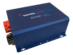
Yes, this is an example of an inverter that makes it really easy.
Notice the little green terminal block on the front left.
Are you considering inverter/chargers or just inverters?
 
My first post here. I had intended on asking some questions in a stand alone thread, but this topic is central to one of my questions so here goes.

Is the contactor used to disconnect the battery from the inverter and if so what triggers it? One of my possible solutions to implementing my system (RV based) is to run a single 280ah battery/120a BMS, wiring a 2000W inverter/charger directly to the battery and allowing the BMS to control it via a solid state relay (SSR), but since the inverter/charger will pass charging current through even when shut off I run the risk of sending current to a cold or otherwise compromised battery.

So my thought was to use the SSR to both shut off the inverter/charger and disconnect the DC line between the inverter/charger and battery. Alternatively, if I am going to disconnect the battery do I need to turn the inverter charger on and off?

So much information in this forum, so much input from experienced people, I am still trying to figure out how to keep up. Great resource.
Thank you.
 
Yes, this is an example of an inverter that makes it really easy.
Notice the little green terminal block on the front left.
Are you considering inverter/chargers or just inverters?
I have a 100ah 4s with a Daly 100amp, I have made light of the Daly but it was cheap. I have a Xantrex Prowatt 600 connected to the batt. This has been used as a gas boiler backup to power circulation pump and ignitor.

So that build has been fine for now but looking to expand to something larger to handle the following:

Peak watt usage per hour, continuous lower perhaps down to as low as 1/3rd.
Furnace - 120 watt
First Floor - 210 watt
Fridge - 250 watt
Aquariums - 230 watt

Those values have been determined using Emporia Vue . Have confirmed with a Kill o watt also and seem to be close, maybe 5% differential. Not sure which one is more precise.
 
Is the contactor used to disconnect the battery from the inverter and if so what triggers it?
The bms controls the contactor.
Contactors are expensive and subject to a lot of current.
I would use another option of possible.
One of my possible solutions to implementing my system (RV based) is to run a single 280ah battery/120a BMS, wiring a 2000W inverter/charger directly to the battery and allowing the BMS to control it via a solid state relay (SSR), but since the inverter/charger will pass charging current through even when shut off I run the risk of sending current to a cold or otherwise compromised battery.

So my thought was to use the SSR to both shut off the inverter/charger and disconnect the DC line between the inverter/charger and battery. Alternatively, if I am going to disconnect the battery do I need to turn the inverter charger on and off?
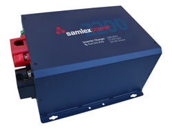
The samlex evo series are excellent inverters and make this a non issue.
They are modal by design, meaning they either charge or invert but not both at the same time. Clever on their part to use the same expensive and beefy h bridge transformer for both purposes.
I worked out how to wire this up with an SSR a few monthes back.
 
I have a 100ah 4s with a Daly 100amp, I have made light of the Daly but it was cheap. I have a Xantrex Prowatt 600 connected to the batt. This has been used as a gas boiler backup to power circulation pump and ignitor.

So that build has been fine for now but looking to expand to something larger to handle the following:

Peak watt usage per hour, continuous lower perhaps down to as low as 1/3rd.
Furnace - 120 watt
First Floor - 210 watt
Fridge - 250 watt
Aquariums - 230 watt

Those values have been determined using Emporia Vue . Have confirmed with a Kill o watt also and seem to be close, maybe 5% differential. Not sure which one is more precise.
Is there a question in there?
 
I have a 100ah 4s with a Daly 100amp, I have made light of the Daly but it was cheap. I have a Xantrex Prowatt 600 connected to the batt. This has been used as a gas boiler backup to power circulation pump and ignitor.

So that build has been fine for now but looking to expand to something larger to handle the following:

Peak watt usage per hour, continuous lower perhaps down to as low as 1/3rd.
Furnace - 120 watt
First Floor - 210 watt
Fridge - 250 watt
Aquariums - 230 watt

Those values have been determined using Emporia Vue . Have confirmed with a Kill o watt also and seem to be close, maybe 5% differential. Not sure which one is more precise.

DARN fat fingered the Post button. Was switching between windows. Sorry about that.

So would think I am looking toward an inverter/charger at best if finances allow but may just have to stick with inverter. Have been changing the current 100ah with a 10a AC to DC charger. Again this is just an emergency backup so not used often and not for too long.

Idea would be to upgrade to a 280ah 12v 4s battery bank. As far as an inverter to allow some headroom would think that at least a 1200 watt would be necessary but maybe just jump up to the 2000 watt as more options available.
These are imho excellent.
I own a Samlex pst, if my usage model wasn't so weird I would have used on of these.


Why use a massive expensive contactor or heavy-duty BMS?

I have connect the inverter directly to the cells, bypassing the BMS.
This way, the BMS can be a regular one (120A will probably do fine) and the BMS isn't subjected to the high inrush currents of the capacitors.

Just use the BMS to switch/connect a small relay, I used an Omron G5V relay, draws only 150mW and is only a few bucks, compared to 5-8W and $200 or so for a Gigavac one.

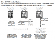
Most inverters can be remote switched. The Samlex eg:

Just connect the small relay (powered by the BMS) to terminal 4A.
Cell OVP, low or whatever, BMS trips, relay releases, inverter shutdown, just as it would if powered by a Gigavac or similar.
Only you save space and $$

You probably can use the second figure as well, even not needing the small relay. (But my inverter didn't have that option so I opted for the relay option)

1615996064019.png
 
So my question/thought is would it be better to build 100ah packs with Overkill 120amp BMS and run them in parallel?
That seems to be a popular scenerio here. It offers the other benefit of redundancy.

I think I recently read that you can give each Overkill BMS a different name and be able to monitor each on uniquely.
 
The bms controls the contactor.
Contactors are expensive and subject to a lot of current.
I would use another option of possible.

The samlex evo series are excellent inverters and make this a non issue.
They are modal by design, meaning they either charge or invert but not both at the same time. Clever on their part to use the same expensive and beefy h bridge transformer for both purposes.
I worked out how to wire this up with an SSR a few monthes back.
Thank you for bringing the Samlex Evo to my attention. Not only would I be able to delete my AC-DC converter, but I would also be able to remove my Grid/Gen transfer switch. Integration of the solar, and possibly alternator, charging capabilities is also very nice. I do not have deep experience in battery/inverter/solar subjects so it will take me some time to digest the manual. I will research your post on controlling it externally to study. More questions forthcoming I'm sure.

I did scan the manual, and one question I did not see addressed is if the Battery Charger DC inputs can be used to charge the battery when the unit is inverter mode. It seems to the inputs would have to be able to charge, or alternatively become part of the DC potential available to use by the inverter, when in inverter mode. To my inexperienced mind it seems if that were not the case you would not be able to use the power generated by the panels while using the inverter. Can you help me to understand this function better? Probably an obvious answer, but I don't want to assume.
 
I did scan the manual, and one question I did not see addressed is if the Battery Charger DC inputs can be used to charge the battery when the unit is inverter mode. It seems to the inputs would have to be able to charge, or alternatively become part of the DC potential available to use by the inverter, when in inverter mode. To my inexperienced mind it seems if that were not the case you would not be able to use the power generated by the panels while using the inverter. Can you help me to understand this function better?
That is a very good question, I don't know.
I don't own an evo just helped someone with their project last year.
Will see what I can figure out.
 
@MBrown I reached out to Samlex engineering and got this excellent response.

"The EXT DC input on the EVO series is a DC input which is wired (with a current shunt) to the battery terminals on the EVO, so charging on this input will take place as long as the battery continuity is present. The EVO does not control the power on this input, it only monitors it, recording it on the remote and data logging if enabled.


This input should be handled as if it was the battery bank which the EVO is attached to. Any DC power (controlled with a charge controller) attached to this input will “see” this as the battery connection.


The EVO, by default, will reduce the bulk current sourced from an AC source by the mount of current present on this input dynamically. The design intent of this feature is to prevent too much current (combined EXT DC current, + bulk current) to be pushed into the battery bank.

If the battery bank can handle the combined current then the parameter (CHARGE CURVE, EXT CHARGER) can be set to 1= Not affect, this will disable this feature."

Hope that helps.
It sure does. Thank you once again.
 
Back
Top