diy solar

diy solar

Thoughts on my system? Fuses, busbars, battery safety

MartyByrde

Off-Grid Innovator
Joined
May 16, 2022
Messages
151
Location
USA
Hi all,

I will be building this system next week and wanted to thank all the help I’ve gotten from this forum.

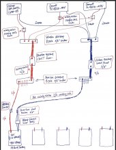
I’ve attached a final blueprint for the system (excluding the solar and AC panel box). I’m planning to have approximately 60 to 80 of the Santan solar 240w panels. Five 6S strings into a combiner box for each of the two Growatt SC48120-MPV charge controllers. VOC will be 223.2V versus 250VDC max. Also three 6S strings into the Growatt SPF 3000TL LVM-ES.

Both charge controllers and the inverter are connected to a BlueSea 600A 8-pole busbar. I used Windy Nation ANL fuses 120A (charge controller) and 100A (inverter). And 2 AWG welding cable.

The five 14kw battery packs are LiFePo4 cells (3.2v 280Ah) arranged 16S. They have the 100A Overkill Solar BMS and I’m using 2/0 cable. I have 200Amp breakers for each battery positive wire but I may need to get a 120Amp breaker instead. I don’t want it tripping too easily because then it will overload the other packs.

All five battery packs are paralleled onto separate BlueSea 600A 8-pole busbars. These battery busbars are connected to the inverter/charge controller busbar by 4/0 wire. This 4/0 has Bluesea 400A Class T fuse on the positive wire and Victron 500A Smartshunt on the negative wire.


Inside the enclosed trailer I plan to ground the three combiner boxes, panel box, and the trailer frame to an 8ft copper bar outside the trailer. The three combiner boxes will be inside the enclosed trailer.

The solar panels will be grounded separately to an 8ft copper bar.


Any thoughts are greatly appreciated!F90A4876-DFB7-42F6-AC9A-C382367E66EB.jpeg
 

Attachments

  • 2022-08-09 15-47.pdf
    442.5 KB · Views: 20
Sounds like a well planned system. The only thing that I would change is not separating the grounding. It should all be one grounding system. If there's a nearby lighting strike, it will create a gradient voltage through the earth. It could travel up one ground rod, through your system, and back down the other ground rod. Because your system has less resistance than the earth.
 
Sounds like a well planned system. The only thing that I would change is not separating the grounding. It should all be one grounding system. If there's a nearby lighting strike, it will create a gradient voltage through the earth. It could travel up one ground rod, through your system, and back down the other ground rod. Because your system has less resistance than the earth.
Thanks. So essentially have the copper wires on the panel arrays run about 20-40 feet from the arrays to the same grounding rod next to the trailer?
 
This seems like a tremendous amount of battery backup and solar for a single 3000 watt inverter. You're looking at over 15KW of solar and 67KWh worth of storage. What is your use case? You never intend to draw over 3000 watts of power?

At say 15KW from solar @ 48V (will be higher), you are looking at >300A going over that 4/0 cable (assuming no direct inverter usage). This is actually above the rating of a 4/0 wire at any length (260A). You may need to run two cables instead (like 2 x 1/0).
 
Thanks. So essentially have the copper wires on the panel arrays run about 20-40 feet from the arrays to the same grounding rod next to the trailer?
Everything should come together at a main ground bar. (Possibly in the service panel) and a single #6 wire from there to the ground rod.
 
This seems like a tremendous amount of battery backup and solar for a single 3000 watt inverter. You're looking at over 15KW of solar and 67KWh worth of storage. What is your use case? You never intend to draw over 3000 watts of power?
It’s for an off grid data center. I’d like to have a 2500w load running continuously, with around 24 hours of battery backup.
At say 15KW from solar @ 48V (will be higher), you are looking at >300A going over that 4/0 cable (assuming no direct inverter usage). This is actually above the rating of a 4/0 wire at any length (260A). You may need to run two cables instead (like 2 x 1/0).
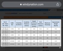
Windy Nation has the 4/0 max amperage of 440 amps. Do you think I should do two cables between the busbars?
 
Everything should come together at a main ground bar. (Possibly in the service panel) and a single #6 wire from there to the ground rod.
Okay thanks I’ll need to research how to do this properly. I was thinking that the panels needed to be grounded at the arrays.
 
It’s for an off grid data center. I’d like to have a 2500w load running continuously, with around 24 hours of battery backup.

Ah, that makes sense. I'm not sure if running an inverter at >80% capacity at all times will live long...don't have experience with that.

Windy Nation has the 4/0 max amperage of 440 amps. Do you think I should do two cables between the busbars?

All the ampacity charts I see show 260A @ 90C. I actually ordered Windy Nation 1/0 cable for my own project and saw that chart on Amazon. I'm not sure if 440A works continuously ... they use the term "maximum amperage", which I don't find comforting. I'm going off NEC charts that are maybe more conservative?


I think it may be smart to look into multiple cables instead of a single 4/0.
 
None of the cables will see more than the amperage draw from the inverter. And the OCP will protect against a short circuit.
 
Ah, that makes sense. I'm not sure if running an inverter at >80% capacity at all times will live long...don't have experience with that.
Yes I don’t know either. I’m going to aim to keep it under 80%.
All the ampacity charts I see show 260A @ 90C. I actually ordered Windy Nation 1/0 cable for my own project and saw that chart on Amazon. I'm not sure if 440A works continuously ... they use the term "maximum amperage", which I don't find comforting. I'm going off NEC charts that are maybe more conservative?


I think it may be smart to look into multiple cables instead of a single 4/0.
Here’s the chart image from Windy Nation and the link to the website:
Windy Nation 4/0
 

Attachments

  • 8B83A04B-5DE1-471F-8233-6541FF5CB63C.jpeg
    8B83A04B-5DE1-471F-8233-6541FF5CB63C.jpeg
    398.4 KB · Views: 18
Yes I don’t know either. I’m going to aim to keep it under 80%.

Here’s the chart image from Windy Nation and the link to the website:
Windy Nation 4/0

Yep, that's on Amazon as well. You may want to email them on that as it conflicts with the NEC chart. The difference may be if they are rated for a much higher temperature which increases ampacity.
 
Good catch, I missed that.
If max charging from all three, it could be too much.
I just emailed Windy Nation to verify it is in fact 440 max amperage for the 4/0. If they confirm 440 max amperage, 320 amps would be 73% so do you think that’s safe?
 
I just emailed Windy Nation to verify it is in fact 440 max amperage for the 4/0. If they confirm 440 max amperage, 320 amps would be 73% so do you think that’s safe?

Use a few of those watts for a fan blowing on them, problem solved. ?️
 
Ah, that makes sense. I'm not sure if running an inverter at >80% capacity at all times will live long...don't have experience with that.


All the ampacity charts I see show 260A @ 90C. I actually ordered Windy Nation 1/0 cable for my own project and saw that chart on Amazon. I'm not sure if 440A works continuously ... they use the term "maximum amperage", which I don't find comforting. I'm going off NEC charts that are maybe more conservative?


I think it may be smart to look into multiple cables instead of a single 4/0.
NEC is very conservative (assumes you are running 300'), solid core and for AC. Google for your choice of charts but make sure it is SAE and for DC.

In most homes the cable to the electric stove is the same size as the power companies cable into the house. Power companies rely on physics not NEC.
 
Last edited:
I just emailed Windy Nation to verify it is in fact 440 max amperage for the 4/0. If they confirm 440 max amperage, 320 amps would be 73% so do you think that’s safe?
Without knowing all the lengths, cabling is way oversized. First give away is the 2/0 cable and a 200 amp breaker. A breaker is meant to protect the cable from it's max capacity. From a weak memory, 2/0 cable can handle 900 amps at something like 60 feet. that would be with a 20% voltage drop. 10% drop is something like 35 feet. Find a good DC SAE cable chart and look at your cable runs again. Seat of the pants you could almost wire this up with 6ga, but maybe 4ga to reduce voltage drop.

You are also not going to get a 2ga cable into the Growatt 3000, been there done that, the routing is awful.

If there is no expansion planned, take a step back and design cables and breakers for maximum draw (heck if if there is expansion planned, max draw). Right now your max draw is the 3k Growatt and about 70a according to their specs (from memory) and hence why I mentioned 6ga. Also try to keep only one or two cable sizes. Saves on cost of cable, lugs, etc. If you never worked with 2/0 or worse yet 4/0 not fun to route, crimp or deal with in general.
 
VOC will be 223.2V versus 250VDC max. Also three 6S strings into the Growatt SPF 3000TL LVM-ES.
Maybe someone can chime in here, but IIRC the max VOC of the PV string should be 25% below the max MPP input DC voltage, to allow for peaks ie during times when the panels are cold but the incoming incident radiation is near peak. I am not too familiar with the Growatt unit, perhaps the 250VDC is not the max.
I found with my set up (using MPP Solar LV 6048) the MPP tracking appeared to operate better by keeping the string voltage lower, which seems to leave the MPP more room to adjust and max the IV curve. Although my Inverter max PV is only 145VDC.
It's 89%.
I generally shoot for 85%.
Just depends on how cold it gets in winter in that area.
 
Back
Top