I think this is the simplest and most effective system I've seen so far!
You have one actuator in the middle of each panel right? Because they go up on the longer side.
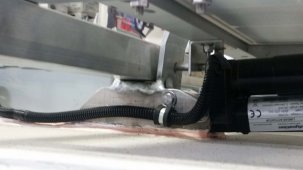
Yes, I have a uni strut that goes all the way across the camper and angles the panels sit on for strength laterally. One actuator per side of the camper to prevent any twist. Uni strut fits into a saddle in the back which doubles as the mount for the actuator. It is quite simple. I used stainless 3/8" rod for the long pin, it's what I had laying around.
Do you know roughly how heavy it is?
I'd like to understand how much weight is needed and if it's worth it for the advantage of tilt compared to just "overpanel"
It's not that heavy really, those actuators have plenty of power. Doesn't even draw full amps.
I totally get you don't have time to write a comprehensive thread and that's probably too much to ask. I think I got the basics of it, then of course every system is different based on the space and size of panels, so we all need to do our part.
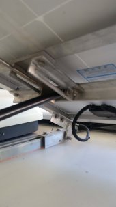
The actuator will easily handle it. You want the hinge pivot as low as possible to get the leverage and the actuator pivot near the roof as low as possible. I had made some brackets 2 months prior as I was planning a trip and then when I finally went to make the rear saddle, I decided to just order some actuators and ended up making the hinges as there are now. I was planning on using a different setup but decided I wanted a self locking mechanism of some sort. That's how this went, I really had no idea what I planned on using. These are 100w Renogy mono panels. The reason these were chosen was I can just get 4 across the roof of the camper side by side and have 2 rows thus far. Maybe a third row is coming but would require a rack to clear the ventilation fan, shower skylight and fridge vent.
I would have mounted flat except the roof air would have shaded one panel. And I planned on heading to AZ and TX in the winter when the sun was low on the horizon and heard many found the output in the winter just was a little short.
I have purchased the Senville mini split but it will be a month or more before I work on that install. Have a wedding to attend in 3 weeks plus I could use a vacation. When the roof air comes off, I have 2 more panels to install in between. That will give me 800 watts total.
For the actuators, I used the 20 inch ones here:
https://www.windynation.com/Linear-...-Momentary-or-Maintained-Up/-/2178?p=YzE9Mjg=
Those will tilt the panels a full 90 degrees. You could go shorter if you only want 45 or 60 degrees which would help on the initial move up off the saddle. You might be able to get by with 12 inch. I had hinges made and wanted the full 90 degrees so I could stand the panels straight for cleaning the roof and access for anything I needed to do for repairs. So I just tilted them up and measured what length I roughly needed to get to 90 degrees. With a shorter actuator you could sit closer to the roof, however you really want 3.5 to 4" under the panel to clear the motor which will be on the top. I've included a photo of the base so you can see how that was made.
I used the momentary switch but would have preferred the Maintained UP/DOWN instead as I set it up to turn off each actuator auto when retracting.
On a side note, anyone know why the Dicor turned pinkish color? Drives me nuts.


") . BTW, it's a testbed now, and yesterday, a rainy day, I had 6 100W 17 Vmp panels on top, charging a 24V lithium ion battery system through a Epever Tracer AN 40A, and tried 3S 2P instead of my customary 2S (because I keep hearing it's going to be better). It wasn't obviously better, in several trials. Far from controlled, I know, but, it's not encouraging me to spend time, which is evidently in very short supply around here, on making a better test.
. BTW, it's a testbed now, and yesterday, a rainy day, I had 6 100W 17 Vmp panels on top, charging a 24V lithium ion battery system through a Epever Tracer AN 40A, and tried 3S 2P instead of my customary 2S (because I keep hearing it's going to be better). It wasn't obviously better, in several trials. Far from controlled, I know, but, it's not encouraging me to spend time, which is evidently in very short supply around here, on making a better test.