diy solar

diy solar

Time for a new weather station?

That's a bit brain bending.... dang! Is this because pressure itself is logarithmic?

No, it's just how accuracies are expressed regardless of the sensor they apply to ;)

The datasheet of the $100 sensor says the max error is .2% FS (full scale) where FS is 3500 Pa and 1.5% of the measured value (reading).
So, you're right I was taking .2% of the full scale and applying it at the bottom.

So, the accuracy error accumulates as the voltage goes up..., that is at 0 mV when there's no wind so 0% error?
At the max reading that's the max error (.2% of 3500 Pa)?

Saying 0.2 % FS for a 3500 Pa sensor is the same as saying 7 Pa. So the total error can be expressed as 1.5 % + 7 Pa. For example if you measure 200 Pa then you can have a max error of 10 Pa (1.5 % * 200 + 7).

At 0 Pa real the 1.5 % error disappear but you still have the 7 Pa error.

Usually the base offset can be calibrated and never changes much so you only deal with linearity error.

BTW 3500 Pa is a bit much so I'd recommend a 1500 or 2000 Pa one, and you can find sensors with a better accuracy, both of which will give you better results.

I'm concerned that it would cost more to buy a signal generator and an o-scope than it would be replacement parts.

No need of a sig gen, just toggle a arduino pin at 40 kHz ;) But the scope is almost mandatory if you do stuff like this, else it's like driving while being blinded... You can find used 2x 20 MHz scopes for next to nothing on ebay/craig list/... (or even free if you know someone who handle that stuff in universities and co for example) which would cover 99 % of your basic needs (and 100 % for this project). EEVBlog has a good video about finding them ;)
 
Thanks for explaining that, one less rube mistake to make!
...it's like driving while being blinded...
So situation normal... why do you think I'm so eager for self-driving cars?

Okay... so I might be able to afford next to nothing, depends on wide next is. Thanks for those tips...I'll have to start shopping for one ... if they're that inexpensive a working one would be a nice addition to the horde.
 
Found a 2x20 scope for $25...but it would take too long to get here... $80 shipping so I'm assuming it's coming from Mars. Nada on Craig's list... but... now that I'm thinking about it... I think one of my DMMs hooks into my PC... need to check into that.

But, I did bump into this $50 daughter-board that uses a PIC16F628 as the Time Of Flight calculator. I see the LM358 to boost the reciever's output voltage, but looks like it's setup for 5V transponders.

Update: Link to the EEV blog on how to find an anaolog scope for < $50. I must not be trying hard... couldn't find one.
Technically one isn't needed as the Teensy could be a 14 channel 100 MHz oscilliscope with the addition of a $15 color display and some wires. Here's a nicely done non-teensy version with a pot, and here's a teensy prototype.

Update 2: According the manual, my DMM can measure upto 60 MHz frequency and also the duty cycle. Never used it at those speeds, have to admit I'm a bit dubious. It did connect up to my PC and display values so that was something...
 
Last edited:
Testing Transducers - Caveman Electronics Part II

Theory
- Rapping a transducer should make it "ring", like a guitar string after being plucked. The ring should produce measurable voltage for a brief time at a frequency, probably some harmonic of it's design frequency. Using a DMM with a Hz setting whose scale covers at least that of the transducer (40 kHz in this case), you should see a reading.

Practice - My cheapo everyday DMM got a reading on a couple, not every tap produced readings, about 1 in 4. My expensive DMM was able to see a frequency on all of them, typically one to three different values as the ring dampened.

Note: After testing I recalled seeing in the datasheet that the transducer was designed to minimize ring, with a maximum ring of 1.2 ms.

Why Caveman? Well, I'm literally pounding on it with a club... ;-)
 
Last edited:
Well, if you can't find a nice used one then get a cheap crappy USB one (well, not too crappy...). You can also use a sound card but they are very BW limited and always AC coupled, so unless you have a nice one who can go higher then 40 kHz is a bit too high as audio stops at 20 kHz...
 
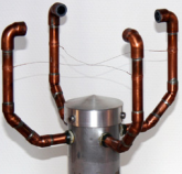
Having taken a week off from this (fishing & stuff) I'm looking at it from a new angle. Designs like this one have inherent mechanical problems:
1595943343710.png
That is heat/cold would expand/contract the arms, wind would make them flex, street/wind vibration, wind interference could put them out of alignment. Each factor needs some sort of correction based on temperature, direction of the wind, etc.

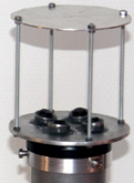
Seems that a design like this would help minimize those problems:
1595943477341.png
Now any vibrations would move all the sensors together so would be canceled out. The legs are thinner so less wind interference, although the distance to the reflector would still change with temperature and could vibrate independently, although that might be a couple ofcorrection factors based on Temperature and windspeed.

Is there an even better design? Perhaps move (remove?) the legs farther out and increase the distance? Use a nearby object (neighbor's house) as a reflector?
 
Looking at the lower power Max35103 ToF chip it and it's minimum receiver voltage is 10 mV. From the numbers in post #22, 3.3V on the transmitter would only generate 8 mV at the receiver and 5V just squeaks in at 13 mV. The typical receiver voltage for the ToF chip is 700 mV, so looks like a ~100x amplifier would be needed. Mr Google shows a few in receiver circuits ... U1741/U1742, bc549, OPA2381... ug... have to figure that out and they'd undoubtedly need tiny bits (e.g., resistors) soldered in... wonder if I can fine a module for a buck or so more...

So earlier a voltage doubler was recommended, every volt helps with the SNR, but that halves the current. The ToF chip can source 50 mA, and the transducer has an impedance of 400 Ohms at 40 kHz, so doubling 3V and dividing we get 15 mA. Doubling again to 12V would be 30 mA.
 
Last edited:
Looking at the lower power Max35103 ToF chip it and it's minimum receiver voltage is 10 mV. From the numbers in post #22, 3.3V on the transmitter would only generate 8 mV at the receiver and 5V just squeaks in at 13 mV. The typical receiver voltage for the ToF chip is 700 mV, so looks like a ~100x amplifier would be needed. Mr Google shows a few in receiver circuits ... U1741/U1742, bc549... ug... have to figure that out and they'd undoubtedly need tiny bits (e.g., resistors) soldered in... wonder if I can fine a module for a buck or so more...

You want to get higher than just the minimum as lots of things will degrade your SNR, margin is good, plenty of margin is better :)

If you don't want to use SMD because the components are too small it's not a problem, just use through-hole parts on a piece of perf or strip board ;)

So earlier a voltage doubler was recommended, every volt helps with the SNR, but that halves the current. The ToF chip can source 50 mA, and the transducer has an impedance of 400 Ohms at 40 kHz, so doubling 3V and dividing we get 15 mA. Doubling again to 12V would be 30 mA.

I didn't recommend voltage doubling but using a full H bridge (4 transistors) instead of just a half bridge (2 transistors) because for the same PS voltage the transducer will get twice the voltage.
 
Doesn't look like the Max35103 chip will work after all, the minimum frequency it'll do is 125 kHz with the 4 MHz oscillator. The other crystal value is to low to get a 40 kHz transmitter signal. Also, in retrospect, don't think the voltage doubler would work on the launcher pin anyway as it would consume most of the pulses just building up the voltage which increase the overall error rate. Oh well....
 
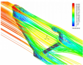
One of the problems with the geometries in #46 is that when the wind aligns to a support bar it interferes with the measurement as illustrated here:
1600188572154.png
The clever folks who wrote this paper asked if the measurements could be enhanced by changing the geometry:
1600188621367.png

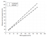
How did it do? Fraksum! "The sensitivity of the developed prototype was 0.049 km/h". It beat out the Gil, one of the best commercial versions available.

1600190541322.png

OMG! They used the 400EP18A... those are the transducers I have...
 
<sigh> Why does the circuit board look more complicated then the diagram?

looks like they built one send/receive circuit for each transducer? Why not just use a multiplexer?
1600191921636.png1600191953374.png

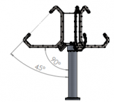
I wonder how accurate 4 transducers using two legs offset at 90° would be? I suppose the when the wind was 45° to one arm would cause interference with the second.... although altering height of the second arm might fix that?
 
Last edited:
...I saw from the Heathkit post that they have weather station parts...
I found a "reconditioned" replacement anemometer for $18 from the manufacturer based on your idea in post #4 ... but this still seems like a cool project so whenever I get a few minutes waiting on something else I delve into it. Possibly someday I'll actually build one.
 
The TDC7200 has two modes, 12 ns precision over 500 ns, or 250 ns over 8 ms. The signal takes over 500 ns, so that leaves us with the 2nd mode. Let's try that calculation backwards to see what the minimum distance would be given t= d/(Vwind + Vsound) for a 1 mph sensitivity

.25 µs = T1 - T0 // from post #13
T0 = d / (344) // 344 is the speed of sound in m/s
T1 = d / (344 + 0.44) // 0.44 is 1 mph in m/s
.25 = d / (344 + 0.44) - d / 344
d = .25 / ( 344 + 0.44) - 1 / 344) = 118,487m

Looks like we can eliminate the TDC7200. Well rats... that was the last ToF chip... perhaps there's another or a high precision counter?
 
Last edited:
Honestly I would use some analog and discrete circuitry to solve that, but I'm a dinosaur... ?

It's basically the same problem as the good old radar, you should look into how they were designed when they didn't had MCU and all that new stuff :)
 
...I'm a dinosaur... ?
A dinosaur who knows what he's doing... I don't have that luxury!

What the authors of that paper did freaked me out:
Thus, we excited it with 40 kHz pulses of 120 V peak-to-peak, present at the transformer output. Also, before reaching the transformer, the excitation signal passes through an RC low-pass filter formed by R4 and C2. This filter has cutoff frequency of 7 Hz and has the function of filtering the noise present in the system power supply2 . In turn, the component D2 is a zener diode and causes the voltage induced by the primary of the transformer during its unloading to be 13 V. This is very important because it causes less distortion in the secondary of the transformer, which is the signal responsible for exciting the transmitting transducer

The datasheet says the maximum continuous driving voltage is 20Vrms. When I first read that I thought they were applying 120V to the transducer, although now I'm thinking the 120V is the input to the transformer and the transducer only saw 13V. Sounds like they filtered the 120V and then the 120:13 dropped any remaining distortion. But I'm a little surprised they'd have to do that; I'd expect the square wave off an MCU to be cleaner. The Arduino seems pretty clean [ref].

I'm thinking using the Teensy again to run a 50% duty cycle to a transistor to drive the transmitter at a higher voltage, then amplify the receiver and use the M7's sample and hold as discussed in post #17. But given what the authors did to clean up the transmit signal I'm betting it won't work well and is going to take an oscilloscope to keep playing with filters and voltages to get right.
 
Well I'm pretty young but somehow prefer the dinosaur solutions in electronics, I hate the "use an MCU and software to solve every problem" approach...

The datasheet says the maximum continuous driving voltage is 20Vrms. When I first read that I thought they were applying 120V to the transducer, although now I'm thinking the 120V is the input to the transformer and the transducer only saw 13V. Sounds like they filtered the 120V and then the 120:13 dropped any remaining distortion. But I'm a little surprised they'd have to do that; I'd expect the square wave off an MCU to be cleaner. The Arduino seems pretty clean [ref].

I think your read right the first time because they say the 13 V is on the primary side and the secondary side (i.e. 120 V) is on the transducer side.

You can do that kind of things if you know exactly what you're doing and/or have asked the manufacturer to confirm it's ok to do that.

But given what the authors did to clean up the transmit signal I'm betting it won't work well and is going to take an oscilloscope to keep playing with filters and voltages to get right.

Yep, IIRC I told you earlier you'll need an oscilloscope for this kind of project. But the good thing is that given the frequencies used you only need a very basic one ;)
 
In looking at the diagram again you've got to be right... looks like a 12V power source driving the circuit.

From their paper the distance is 20 cm, using the sound pressure level calculations in #22 for a few voltages using a distance of 20 cm we get the table below (The 120V is way out of spec from the datasheet so dubious at best for it):

transmit VSPL VSPL ΔdSPL loss ΔdλSPLμbarReceiver mV
3​
-10.5​
6.0​
0.037​
103.5​
30.0​
5.34​
5​
-6.0​
6.0​
0.037​
108.9​
50.0​
8.90​
7​
-3.1​
6.0​
0.037​
110.9​
70.0​
12.46​
10​
0​
6.0​
0.037​
114.0​
100.0​
17.80​
13​
2.3​
6.0​
0.037​
116.3
130.1​
23.1​
15​
3.5​
6.0​
0.037​
117.5​
150.1​
26.71​
20​
6.0​
6.0​
0.037​
120.0​
200.1​
35.61​
120​
21.6​
6.0​
0.037​
135.6​
1200.5​
213.68​
1600257773782.png

Could the noise really be so bad they'd need 213 mV at the receiver? After all, AM/FM is in the μV; if your using an amplifier that just seems crazy... is this what happens when you put 7 EEs in a room? I need to re-read that several more times....
 
Last edited:
...Well I'm pretty young but somehow prefer the dinosaur solutions in electronics, I hate the "use an MCU and software to solve every problem" approach...
Didn't mean to imply you were old, and I do understand what you mean... beauty is in the eye of the beholder and and the artistry of something tangible is far more evident then something intangible like s/w (which far to often isn't very pretty at all).
 
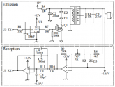
They're using the STM32F429 180 MHz chip, so that's 6 ns/cycle and should be fast enough for 1 mph wind speeds deltas. On the transmitter, they're using the MCU as a signal generator to R1. From there it goes through a non-isolated driver U1 to protect the micro-controller. That feeds MOSFET Q1 which excites the 1:10 transformer. R4 and C2 form a low pass filter with a cutoff at 7 Hz to get rid of noise in the power supply (battery shouldn't have that problem). R5 and C3 allow discharging the energy stored in the transducer.
That all seems straight forward.

1600271062643.png
Then there's D2 is a zener diode and it causes the voltage induced by the primary of the transformer during its unloading to be 13 V? They say:
This is very important because it causes less distortion in the secondary of the transformer, which is the signal responsible for exciting the transmitting transducer. Empirically we observed that, without the zener diode, the RMS value of the wave applied to the transducer is 8% smaller, resulting in a lower excitation amplitude and causing the reception signal to be more noisy and of lower intensity

Sounds suspiciously like magnetic magic, I get the transformer's magnetic field will resist the change in current flow but not how the zener is bumping the voltage up in combination with it. Tried simulating it (see attachment) but didn't see 13V... to many unknowns. Certainly the output transformer voltage didn't ramp up very fast.
 

Attachments

  • PzTransformer.txt
    1.1 KB · Views: 2
Back
Top