diy solar

diy solar

Top Balancing "How to"

It seems clear that holding high voltage on cells for an extended time causes some degradation. Doing so briefly would be minimal, especially in your climate-controlled workshop.
If you do NOT top balance your cells, then if SCC charges the pack to target voltage and no cells are so high as to cause BMS to disconnect, some cells will be up the knee toward 3.65V while others are down around 3.3V. So not balancing would accelerate degradation, especially if environment is hot.
Maybe passive balancer will make them similar eventually. I would top balance one time to start. That need to be higher not lower than what SCC is going to do.
 
I did fine with the initial charge in series fully protected with the BMS. Bled off power of the top cell along the way. Was quite a horse race, especially as they went above 3.400, and ended very close. After resting I briefly ran it up again and all was within 15 mV at the cut off. However this took quite an effort for a couple hours. No cell was at 3.600 for more than a few seconds. I do see the benefit of parallel balancing. I think I would want far more than a 10 amp charger to do fully in parallel. 10/20 amps per cell would seem more realistic.

Next battery I am thinking to run them up in series to maybe 3.400/3.450 and rewire in parallel for the finale. I don't want to break down the compression stack or take six days to complete.
 
Next battery I am thinking to run them up in series to maybe 3.400/3.450 and rewire in parallel for the finale. I don't want to break down the compression stack or take six days to complete.
I did the serial charge same as you are planning.
I topped off the 8 cells individually without breaking down the pack the next afternoon.
No sweat and worked fine.
 
Read his article - the point of doing this is to spend as little time in the upper-knee as possible. And, the charger is considered to be part of the system when buying large capacity cells, so he's running a 60A unit.
Using a 60amp unit is quite a difference from using a 10amp unit. But using my 12amp unit the time spent in the upper knee, above 3.40 volts, was less than 4 hours during the absorbation statge. How much damage was done? Nobody knows for sure and I suspect it's not measurable.

So we'll just have to agree to disagree. I'll do it my way, you do it yours, and we'll all live in peace!
And I agree. If step balancing would have worked for me I would have done as suggested in those articles. And it might have using a high amp power supply, something I wasn't willing to invest in for a one time use.
 
The reason I think some step method is best is that if you can get all the cells to 3.4V and have them fully absorb all the energy they can, you can be somewhat assured that they are at the same level of charge at 3.4V. Same thing when you step again up to 3.5V. Then when you go up to your final top balance voltage you are on the steepest part of the curve, and all the cells should be together. You won't have to leave it at that top balance voltage for as long, because they were all at the same place.
I appreciate your thoughts. But as I posted above the time spent in the upper knee while the cells were absorbing was less than 4 hours. If one cell was at it's full SOC for less than 4 hours, or even a day, IMO no harm no foul. I would rather have the PS in CC mode than in CV mode using the step method. And the common 10amp power supplies have a tendencay to stay in CV mode and output lower amps unless the voltage is set to 3.5 volts or more even if using good cables and terminals.

I also don't think you have to top balance to 3.65V. As long as you are on the steep part of the curve, your final step should ensure that the cells are pretty well top balanced. So I think top balancing to 3.6V, 3.55V, and even 3.5V is nearly as good as top balancing to 3.65V.
I am not so sure about that but you might be right. It would be nice to know the SOC of each cell if parallel top balancing at lower than 3.65 volts. I like low Delta's but I am not OCD when it comes to that.

When I was new at this and before I received my cells, I was against parallel top balancing altogether using a power supply. I thought about buying a 10 amp 3.65 volt charger and using that to parallel top balance or charge each cell individually out of an abundance of caution. But others convinced me to parallel top balance using a power supply so I bought the Riden and have had no regrets and it has come in handy.

In the end it's up the user how they go about balancing....it's their cells. :)
 
Gazoo - have fun. I don't want to be a kill-joy (as my grandmother used to say to me sometimes)

I learned how the lesson of time - if ignored - can bite you later on. In this case, using inadequate current for charging is akin to using vice-grips to build your bank. Or putting regular gas in your Corvette - ad infinitum for bad analogies.

Initial results may seem ok. It's more or less a best-practice kind of thing, to avoid turning your Grade-A cells into Grade-B at the outset.

Anyway, not a big deal. This is more about having fun with LFP than any industrial type concern.
 
You are right that there are probably hundreds of people who encourage either top balancing or bottom balancing, and most of them associated with solar would argue for top balancing. As far as I know, you are the only one that feels it is a really bad thing to do. If you are really an expert on this, there simply has to be some other respected sources for the same argument.

I don't think you are a troll. However, by just tossing out ad hominem attacks at people and not siting evidence, you can be seen as a troll.

Good post, at some stage when i get more time i will compile the data i have into a form that is easily understood.

I previously posted an article explaining the different phases of the lithiaton process and the main drivers of dendrite growth (lithium plating), that included charging a “fully charged” cell.

I have a feeling it went over the head of most readers on this forum.

As i said, i copped more grief for sharing the information (from the same chemist) that it was harmful to repeatedly charge cells into the knee. At that time there were a few BMS manufacturers that had sold many units that worked in this manner - they were adamant it was fine.

I can assure you i won’t get upset if not one single person listens - it won’t affect the packs i build.
 
I have 28, 40Ahr Lifep04 cells to top balance with a 30V, 10A bench power supply.

They will ultimately be connected 7 in parallel, 4 in series to produce a 12 Volt bank.

The cells are currently all at 3.3V, and connected 7 in parallel.

I understand that it is a long process, depending on their current state of charge, and the maximum output of the power supply, but to speed the process up I can connect them in series first, as long as I have the BMS connected and set to disconnect should a cell hit 3.6 or 3.65V. I assume I can only connect seven in series to do this, and then repeat 3 times for the remaining cells. I could then connect the cells in parallel to finish off the process.

My questions are:

1. Would I be better off connecting all 28 cells in parallel to finish the process, or leave them in banks of seven?

2. Would I be better off using the parallel step method on each group of seven cells to progressively get them all near full SOC so as not to leave them fully charged for longer than necessary?

3. Could I connect 7 cells in parallel and charge until the cells hit say 10A before disconnecting and still achieve a reasonable top balance?

4. I currently have a marina electricity supply. Is there a danger to my power supply should that supply be interrupted. Do I need a diode in the positive supply?

5. If I don't want to leave them unattended whilst balancing, can I reduce the voltage, say overnight, or switch off the PSU altogether and continue the process the next day?

6. Should I start a different thread on this?

Thank you
1. You should finish every cell in a battery pack in parallel.
2. Your choice, I have had zero problems just hooking them up and setting power supply to 3.65v.
3. I don't understand this question, the objective is to get every cell in a battery pack to 100% charged.
4. I have never used a diode, but I have reliable power. If you use a diode you must account for voltage drop.
5. If you set the voltage properly there really isn't any danger. If you switch off the power supply, disconnect the cables.
6. Maybe.

My advice is to hook them up as you eventually will as a pack and charge at 13.8v until the BMS either disconnects or amps in drop under 1. You are 98% done if they aren't seriously out of balance, and having more cells actually works in your favor. Then parallel and finish.
 
Last edited:
Connecting the cells in some series combination first is a way to charge from as-delivered (perhaps 30% to 70% SoC) to somewhere near 100% SoC in less time that parallel charging the entire way. This has to be done with a BMS, so it can terminate charging as soon as one cell reaches 3.65V

Supply can deliver 10A while set for 3.65V, charging 28 cells in parallel, 10A/28 = 0.357A per cell. That's 0.009C for a 40 Ah cell.
This works, just takes more hours.

By assembling the pack 7p4s, same supply can deliver 10A while set for 14.6V, 10A/7 = 1.43A per cell. That's 0.036C
Once BMS disconnects because one group of 7p has hit 3.65V, cells can be reassembled all in parallel to finish charging and top-balance to 3.65V.
This approach saves time because most of the charging occurs at 0.036C, and only the last portion at 0.009C

Alternatively, leave pack assembled as 7p4s, and wire charger to one group of 7p at a time. This doesn't charge any faster or slower, but it avoids breaking down the pack.

Series charging with 7s (or 4p7s) would be faster than 7p4s. However, unless you have a BMS compatible with 7s, you can't do that.
BMS needs to be able to monitor every cell (or group of parallel cells) in the series string.


Some power supplies (especially higher end ones) have a crowbar function, will pull down the output if it is higher than set voltage. Those recommend using a diode when charging batteries.
If you connect a resistor between supply and battery (to limit current to a non-harmful amount), you can measure whether supply lets its terminals be held at battery voltage or not.
You could connect a fuse for extra protection. A 15A fuse is common for PV strings, and would probably protect the transistors of a 10A power supply if it crowbars.

A diode has a logarithmic IV curve. You would set supply higher to account for voltage drop of diode, but that voltage drop varies with current, so battery voltage will continue to rise slowly toward supply voltage. You need to select a voltage low enough that it won't pull battery too high. Using CV/CC capability of supply you can map out the diode's IV curve to determine the voltage drop at some tail current (maybe 0.0001C for the cells). Or read the data sheet. See what difference diode voltage would be at 0.01A vs. 10A
 
Hi,

Can i leave my pack assembled in series as 4s (12v) and charge one by one cell at 3.6v for top balancing like in this video ?

Or do i need to disassemble my pack and charge them separately or in parallele as explained in the first thread ?
Thnx
 
Hi,

Can i leave my pack assembled in series as 4s (12v) and charge one by one cell at 3.6v for top balancing like in this video ?

Yes.

Or do i need to disassemble my pack and charge them separately or in parallele as explained in the first thread ?
Thnx

No.

But leaving them in series with the BMS connected allows for additional opportunity for Murphy to pay you a visit. Just pay attention.

It may take longer since you're doing 4 separate charges.
 
Yes.


No.

But leaving them in series with the BMS connected allows for additional opportunity for Murphy to pay you a visit. Just pay attention.

It may take longer since you're doing 4 separate charges.
I forgot to say that I keep the busbars and BMS wiring, i will only disconnect the BMS.
 
Hi,

Can i leave my pack assembled in series as 4s (12v) and charge one by one cell at 3.6v for top balancing like in this video ?

Or do i need to disassemble my pack and charge them separately or in parallele as explained in the first thread ?
Thnx
Yes, charging each cell individually is a legitimate approach.
You needn't disassemble to do it.

The alligator clips he is using are the best that come with those supplies, which means they are only moderately horrible. Frequently you can double the amps put out by your power supply by using 10 gauge wire and ring terminals. That keeps the current higher for longer, thus speeding up moderately what can be a lengthy process.
 
I have not done it but how about ring terminals and tiny vice grips or c-clamps or similar.
Those alligator clips in the video really are the best set included with the cheap 10 amp supplies. All of the others I've seen are really garbage.
I would clip the leads to the busbars where you get a much better connection, rather than the stainless steel grubscrews.
 
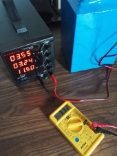
I charged the pack to trigger BMS to the first cell that reach 3.55v, than disconnected the BMS. Now i used bench power supply, set it to 3.6v and charge one by one cell. The cell that i firstly started charging was 3.3v, it takes about 4 amps but i also see that over time the voltage on the bench power supply is slightly dropping. Now it is 3.56v and 3.42 amps left. Is this quite normal ?
 
Last edited:
I charged the pack to trigger BMS to the first cell that reach 3.55v, than disconnected the BMS. Now i used bench power supply, set it to 3.6v and charge one by one cell. The cell that i firstly started charging was 3.3v, it takes about 4 amps but i also see that over time the voltage on the bench power supply is slightly dropping. Now it is 3.56v and 3.42 amps left. Is this quite normal ?

As the voltage of the battery approaches the voltage of the power supply, the amps will drop. This is normal.
 
As the voltage of the battery approaches the voltage of the power supply, the amps will drop. This is normal.
Yes i know that but i was talking about the voltage on the power supply that is also dropping over time. Is this normal ?
Initially, it was set on 3.6v. Now it is 3.55v
 

Attachments

  • 214239710_3730491597051504_4240140597311080119_n.jpg
    214239710_3730491597051504_4240140597311080119_n.jpg
    186.6 KB · Views: 8
Back
Top