diy solar

diy solar

Top Balancing "How to"

After top balance, how can I test out each cell to make sure they are good? I suspect I may have ruined at least one of the cells with an accidental short.
I have a orion bmsjr on the way so plan on a 2p16s setup with 32 of the 300/310ah lifepo4's from hayley @ lightning-power that are currently top balancing with 3.65v @ 8a on one of those lab psu so will take some time. if I have to re-top balance after cell testing thats perfectly fine with me.
 
Last edited:
:ROFLMAO:
Definitely not! 10x the resistance of copper, would likely glow red hot unless 1/2" thick.

Copper or aluminum. Solid or braid, straight or bent to allow expansion. Various benefits of each.
Native aluminum oxide causes problems, wish it was tinned, but same goes for terminals. Various treatments recommended.
Copper reacts with aluminum, so tinned copper is better.
would noalox be a good ide if using copper and alum together? if so, would it need any periodic maintenance or reapplication?
 
would noalox be a good ide if using copper and alum together? if so, would it need any periodic maintenance or reapplication?
I'm no expert, but reliable people here have pointed out that severe oxidation can occur with dissimilar metals, in particular copper on aluminum. It's like at the bottom of the list for compatibility.

It was highly recommended that I make up new main leads with tinned lugs in lieu of plain copper, and apply no-lox or oxgard. Which I did.
My bus bars/cell connectors, were already tinned. [shrug]
 
@atti suggest you make a new thread and I will help you.
That is only a 20 Amp unit and requires a dc supply. I have modified a mains PSU 60 Amp 5 Volt unit to 3.65V by replacing the 1K pot with a 5K. You will need to measure volts and amps. I suggest a non contact ammeter to avoid volt drop. Good practice says the volt sensing should be brought out to make 4-wire "Kelvin" connections and there should be fuses etc. But I am rough and just wanted it done and not a project.
 
For current best practices on top balancing cells, please watch the video and download the PDF at the following page:

Top Balancing Cells Using a Low Cost Benchtop Power Supply

If you are interested in a more general tutorial of what balancing is about and *Why* to balance, check this out:

Explanation for Beginners of Top and Bottom Balance

If you're asking yourself if you should top balance your cells, the answer is always: "YES!" If you don't, it's almost certain that even a small imbalance in the cell SoC will cause "runners" at near full charge and will be VERY frustrating.
very nice pdf thanks. Am compiling a solar home operator's manual for this home for the next generation and this will go in the toolkit. I use a smaller charger (it's what I have), and if I overshoot i use a cheap alligator clip modified sine wave inverter and a space heater to quickly pull down the hot ones (as opposed to the light bulb method)
 
I've top balanced my 16 280Ah cells in two group of 8; I charged at 3.65V with cutoff at 0.8A; obviously I did one group after the other and not at the same time; the first group of 8 is now sitting at around 3.5V after 21hours; the other 8 finished charging 7 hours ago and are at 3.533V; can I already arrange them in series with BMS (Seplos) or do I need the second group to approach the voltage of the first?
 
I'm new to LiFePO4 batteries but experienced with LiPos. I'm building my first pack and am having trouble understanding the emphasis on top balancing and all the effort that goes into what I think of as a simple balance charge. In the RC world the majority of chargers can balance the cells and have presets for LiFe with charge termination at 3.6/3.65V. Most chargers balance by putting charge power through the main leads and then running small discharge patterns on any cells that get ahead of others near termination voltage. It basically keeps knocking them down while the others catch up.
Is it just that people don't have access to a balance charger? In many cases, it's lower cost than the power supplies being purchased for top charging. I started top charging in parallel, realized I was in for a crazy number of hours and then wired the battery in series with a standard balance connector to use with my RC charger. As a 4S pack, it'll take 1/4 the time and the charger will manage the balancing (I haven't attached the BMS yet). It's too bad the BMS doesn't use the JST-ZH balance connectors that are the standard in the RC hobby and then I wouldn't even have to remove and replace the leads - just plug in the BMS after the balance.
The only thing I can think of that might be a factor is running something like a 4S2P config where the charger would balance pairs of cells and you might prefer the top balancing parallel approach. Many of the tutorials are using simple 4 cell configs. Is there something I'm missing about the benefits of top balancing?
 
It’s an effort to get all cells even at peak so the built pack will fully charge without one cell hitting the bms as full and it terminates charging.

RC chargers for lipo cells have balance circuitry that uses the balance leads. A bms is similar but with very limited capacity. An RC pack might be 5 amps charging at 1C, while a lfp battery could be a hundred times that.
 
I have gotten 4 200Ah lishen cells. One was 2.8 V the other 3.0V
I've charged the 2.8 seperate with a small lab power supply.
Next step charging them in series with a Daly BMS till one hits the 3.65 limit.
Top balancing in parallel with the lab power supply went very slow so I needed something more powerfull.

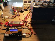
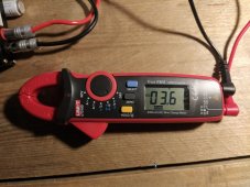
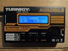
I have a Turnigy accucell 6 wich was used by my son when racing RC cars but no good powersupply. What I did have was a PC psu! Together this speeded the balancing job.
Settings in de Accucell 6: LiFe 1s worked quite well. Max at 5.7A

IMG_20230225_140935.jpg
IMG_20230227_073206.jpg
Finished at 3.61v. The last 0.4v to 3.65v took about half an hour with the lab power supply.
 
Last edited:
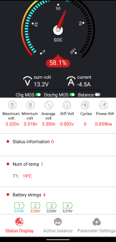
I've assembled the cells back in series, charged the pack and discharged to 50% with inverter and ceramic stove 400-800 Watt. Diff voltage 0,002V.
Now charging again. Until now it looks promising.Screenshot_20230306-212407.png
 
For current best practices on top balancing cells, please watch the video and download the PDF at the following page:

Top Balancing Cells Using a Low Cost Benchtop Power Supply

If you are interested in a more general tutorial of what balancing is about and *Why* to balance, check this out:

Explanation for Beginners of Top and Bottom Balance

If you're asking yourself if you should top balance your cells, the answer is almost always: "YES!" If you don't, it's almost certain that even a small imbalance in the cell SoC will cause "runners" at near full charge and will be VERY frustrating. However, if you follow the guide, you may discover that you may not need to top balance.

If you are building your own batteries, then it's pretty well mandatory to own a Watt/Wh meter, a know value load (resistor), a timer, and a reasonable regulated power supply.

If you are working with USED cells, then it's absloutely mandatory. Each cell will need to be discharged to see where voltage drop off happens, and need to be recharged to see where top voltage is at.

Your specific top voltage MUST be below the weakest cell in the battery, cut off voltage MUST be above the weakest cell in the battery.

This keeps you from damaging an already weak cell further.

I try and group weak cells with weak cells, strong cells with strong cells. This is also the reason for programmable upper/lower limit BMS units... This let's you wring out every bit of use from weak cells.

This is also why I use programmable charge controllers on panel strings. Panel string to charge controller, charge controller to battery. Battery polarity directionally isolated from other batteries 'En Banc'. Charge controller is the first line of defense, the BMS last line of defense for the weaker cells/batteries.

A diode does the isolation job to keep other batteries from trying to overcharge older/weaker batteries, but lets the older/weaker contribute power to the DC Buss.
 
Back
Top