diy solar

diy solar

Topbalancing help:)

snailturtle

New Member
Joined
Feb 23, 2021
Messages
1
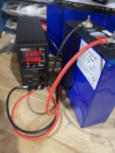
First time posting! I need some help. I'm currently top balancing my 3.2 volt 105ah new lifepo4 batteries.

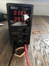
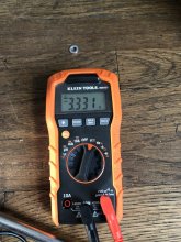
Their original state of charge was about all 3.29 v or so. After a hour of charging it is up to 3.333. My concern is that my DC bench charger is only give out .971 of current. When I started it was a little higher, like .98 or so. My understanding is that the batteries dictate how much current it receives and that once the current drops to .1 the cells are considered charged. However, since the charger is capable of charging by up to 5a the current rate seems pretty low and that this process is going to take forever...

Does this seem sensible to those seasoned veterans of the solarverse. Is something wrong with my DC charger?? Any help would be appreciate!
IMG-1402.jpgIMG-1403(1).jpgIMG-1404.jpg
 
Anticipating your next question...
105 amp hours * .5 state of charge * 8 cells / 5 amps = 84 hours
 
Plus the power supply is in CV mode. It should be in CC mode. And as a reminder, the voltage of the power supply must be set before connecting it to the cells or damage to the cells will result due to being over charged.

What should be happening is once the power supply is connected to the cells, the voltage displayed on the power supply should be a bit higher than the voltage of the cells. Like .1 to .3 volts higher for example.

As the cells charge, the voltage of the power supply will increase until 3.65 volts is reached. Once 3.65 volts is reached, the power supply should switch to CV mode and during the end of the charge the current will drop.

As @smoothJoey indicated, your cables are most likely the problem. You have a 5 amp power supply using 18awg cables that came with it.
 
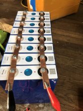
I think the charge leads ALSO need to be on opposite ends of the bank to charge <more> evenly.
Negative lead on cell 1, positive lead on cell 8.
I don't see this often enough for how much sense it seems to make. I became concerned during my first 4S build balance very recently and there was noticeable difference consistently down the line. I was checking every so often... I decided to move the leads to the 2nd and 3rd positive and negative and things cam back together perfect quickly and to full charge. Doing it again I would do just as you suggest. And with larger lead wires as they said.
 
I bet those leads are <20 gauge (with thick insulation). I would go to 16 or greater gauge. 12AWG would be a good choice.
 
What do you have the current (amps) set to on the power supply? I've got the same brand power supply in the 10a version and I think it works a little different than some of the other models people are using. Here is what I see from mine:
  • You can adjust the target (max) voltage or current at any time, it does not need to be disconnected to make the adjustments. You will see the target value change as you are turning the knob and then it will go back to the "live" display as soon as you stop making the adjustments. I've heard others say their power supplies must be disconnected to change settings, but you can change settings as needed and see the changes in the display.
  • If you want to see what the current settings are without moving the knobs, just press the "output" button to turn off the output and the display will show current settings. Again, I don't think most of these cheap power supplies have an output button, but it's a nice feature to quickly confirm settings or just turn off the output if you need to move the connections to another cell.
  • When the power supply is able to push the amps it is set to, it will show "CC" (constant current) and display the set amps and the actual voltage. As soon as it's unable to push the set amps, it goes into CV (constant voltage) will show the amps it's pushing and will display the set voltage. I don't know if that's how other models work, but that's what I see from mine. It looks like yours is in CV mode and you have voltage set to 3.65 and have current set to something higher than .97a. If you turn the amps down to .5, you should see it switch to CC and display .5a and the output voltage (which should be pretty close to the cell voltage).
From what I'm seeing in your current display, I also suspect your leads/clips are only allowing the power supply to push .97amps. You need to make some proper leads. I used 10 gauge wire with ring terminals. See pic below.

IMG-0566.jpg
 
What do you have the current (amps) set to on the power supply? I've got the same brand power supply in the 10a version and I think it works a little different than some of the other models people are using. Here is what I see from mine:
  • You can adjust the target (max) voltage or current at any time, it does not need to be disconnected to make the adjustments. You will see the target value change as you are turning the knob and then it will go back to the "live" display as soon as you stop making the adjustments. I've heard others say their power supplies must be disconnected to change settings, but you can change settings as needed and see the changes in the display.
  • If you want to see what the current settings are without moving the knobs, just press the "output" button to turn off the output and the display will show current settings. Again, I don't think most of these cheap power supplies have an output button, but it's a nice feature to quickly confirm settings or just turn off the output if you need to move the connections to another cell.
  • When the power supply is able to push the amps it is set to, it will show "CC" (constant current) and display the set amps and the actual voltage. As soon as it's unable to push the set amps, it goes into CV (constant voltage) will show the amps it's pushing and will display the set voltage. I don't know if that's how other models work, but that's what I see from mine. It looks like yours is in CV mode and you have voltage set to 3.65 and have current set to something higher than .97a. If you turn the amps down to .5, you should see it switch to CC and display .5a and the output voltage (which should be pretty close to the cell voltage).
From what I'm seeing in your current display, I also suspect your leads/clips are only allowing the power supply to push .97amps. You need to make some proper leads. I used 10 gauge wire with ring terminals. See pic below.

View attachment 43161
Nice explanation of the operation of that supply.

The cables and connections will make a large difference.
 
First time posting! I need some help. I'm currently top balancing my 3.2 volt 105ah new lifepo4 batteries.

Their original state of charge was about all 3.29 v or so. After a hour of charging it is up to 3.333. My concern is that my DC bench charger is only give out .971 of current. When I started it was a little higher, like .98 or so. My understanding is that the batteries dictate how much current it receives and that once the current drops to .1 the cells are considered charged. However, since the charger is capable of charging by up to 5a the current rate seems pretty low and that this process is going to take forever...

Does this seem sensible to those seasoned veterans of the solarverse. Is something wrong with my DC charger?? Any help would be appreciate!
View attachment 43116View attachment 43117View attachment 43118
Oddly enough, the description of the supply on Amazon even states the supplied leads can't carry more than 6 amps. This is (as everyone else told you) a significant limitation, you need better leads. At least they do mention it in the description (like fine print, but it is there).
 
We've helped some other people through these same doubts, @snailturtle . See here:
https://diysolarforum.com/threads/first-time-build-280ah-“it’s-alive-”.18995/

It is not a problem that you use narrow wires, it will just take longer because the power supply will switch to CV mode when the voltage of the cells plus the ohmic voltage drop in the wires exceeds the voltage set point. The end effect will be the same though. With fatter wires that ohmic voltage drop would be smaller and it would stay in CC mode a bit longer.

If you don't mind waiting marginally longer you can just proceed and be patient. In general it's a bad idea to turn up the voltage of the power supply to counteract this, so don't do that.

Personally I bet most of the resistance is the alligator clips having limited contact surface, and not the gauge of the wires. But it's easy to check where the voltage drop is occurring by probing the voltage differentially across a few points with your multimeter while it is charging (ex: power supply leads, alligator clip handles, bus bars near the alligator clips, bus bars far away from the alligator clips). Wherever you see the biggest drop as you move down the chain tells you the thing you just crossed over is dropping the most voltage and is therefore the highest resistance part of the chain.
 
Last edited by a moderator:
If you don't mind waiting marginally longer you can just proceed and be patient. In general it's a bad idea to turn up the voltage of the power supply to counteract this, so don't do that.
It looks like he's currently able to charge at less than 1a. If each of those cells need another 50Ah to hit capacity, he's looking at over 400 hours of charging (assuming Amps don't drop further as the cells get closer to capacity). That's asking for a lot of patience. Personally, I'd make some new leads and cut that time down by at least 75%.
 
It looks like he's currently able to charge at less than 1a. If each of those cells need another 50Ah to hit capacity, he's looking at over 400 hours of charging (assuming Amps don't drop further as the cells get closer to capacity). That's asking for a lot of patience. Personally, I'd make some new leads and cut that time down by at least 75%.
Ah yeah 1A is pretty low. I bet it’s not still 50Ah per cell remaining though. A quick glance at a charge curve suggests it’s about 10% of capacity remaining at 3.33V. Still, point taken it would take a long time.
 
Just a note on rings vs alligator clips. I was able to push full 10amps from my bench supply (Longwei) just by jumping up to 12awg and using copper alligator clips on the leads. I am not sure rings are really necessary, at least not up to 10 amps anyway.

I tested on another thread here, and saw about a 5 amp difference just going from the factory stainless steel alligator clip leads to homemade leads with copper clips.
 
Personally I bet most of the resistance is the alligator clips having limited contact surface, and not the gauge of the wires.
But wouldn't 9amps (x 3.65v = 32w) of energy lost into the clips be obviously warm or more likely hot?

It would be like a 30w soldering iron ... obviously hot.

EDIT: This has been corrected in post 22.
 
Last edited:
Where did you get 9 amps from? The OP was at 3.65 and almost 1 amp.
Thanks for keeping me honest, i got confused with another charging thread.

the charger is capable of charging by up to 5a
Ok 4amps of loss (x3.65 = 14.6w).... still obviously very warm if not hot.

So the comments above suggest that the alligator clips' resistance was the source of the low charging amps. That loss is pretty measurable and even with fingertips at this level, easily detectable.

EDIT: This has been corrected in post 22.
 
Last edited:
Sorry to be picky, but where did you get 4 amps from?
5amps charging capability but only producing .97a charge current.

But thinking about this more, if there were 1 amp going into the battery and 4 amps loss thru resistance, why wouldn't this "total current of stated 5amps capability" be displayed on the power supply? The PS has no idea where the current is going...
 
Back
Top