diy solar

diy solar

Topbalancing Help

LoganM

New Member
Joined
Dec 10, 2021
Messages
9
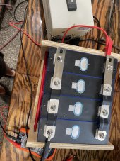
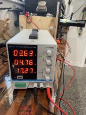
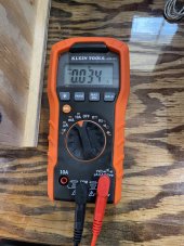
Hello, I’m working on my first battery build and I’m having some issues topbalancing with my 230ah Eve cells (LF230). I purchased a cv/cc charger and began charging my cells in parallel at 3.65v. After charging for multiple days, the batteries have barely charged. Overnight while they are not plugged in, they lose about 0.02v but quickly regain it when charging in the morning. However, the rest of the day is very slow. I used my multimeter to check the current and it shows that the charger is outputting 0.034a (When touching the alligator clips). I’m not sure if I’m using the multimeter wrong, if my charger isn’t working or my cells are bad. Thank you for any advice!

40B9EB0B-5BAA-4EFA-A267-331733DA1147.jpeg851C879C-66BD-46B1-8D18-A434B2C7CE02.jpegB910A4FE-B83D-4566-9220-B976DDBB6712.jpeg
 
1- the wires that come with the power supply aren't really big enough to charge at the full 10a. Most make new wires.
2- you can connect your batteries in series with the bms and charge them. Then put back in parallel to finish top balancing.
 
This is a common complaint, but I am confident nothing is wrong.

Looking at your power supply, you 4.76A going into the cells.
This is being divided into 4 cells so you have about 1.2A going into each cell.
Cells are typically shipped at about 60% state of charge so each cell is going to need about .4 * 230 = 92Ah to get charged.
At 1.2A, it will take 92Ah/1.2A=76.6 hours to charge.
Since the cells are not being charged overnight, I'll assume they are getting 16 hours/day of charge. That means it will take 76.6hours/16= 4.79 days.

Can this be spread up? Yes:

1) Set them up in series with the BMS and charge them at 14.6v and max current the supply will provide till the BMS kicks off with an overvoltage on one of the cells. Notice that when you are doing this, you are pumping as much as 146W into them. (Your existing set up is only pumping 17.27 W into them.). Once the BMS kicks off, the cells will be closer to full charged. Now put the cells back in parallel and do the top balance.

2) Build heavy duty leads for the power supply. The voltage drop on the leads makes a big difference.


You may want to review this resource:
 
You may wish to check your multimeter documentation on using the 10a scale-your leads are not connected correctly.
 
I’m not sure if I’m using the multimeter wrong, if my charger isn’t working or my cells are bad.
2) Build heavy duty leads for the power supply. The voltage drop on the leads makes a big difference.

If those are alligator clips, in addition to the heavier gauge wire like 10 AWG, I recommend attaching with a bolt and not an alligator clip. In my case, for my leads for my particular power supply and battery studs, I used M6 ring terminals crimped on each end of 10 AWG wire. M6 is about the same size as 1/4".

I went from constant current of 3.6 amps to 10 amps by replacing the leads on my 10 amp power supply. Results are typical.

 
I see on the other thread that you updated the power supply leads and the current maxed out. 10A is double what you were showing before so you should see things speed up...... but be patient.

Even with the better leads, there is a voltage drop from the power supply to the cells. This is normal and expected. Do not try to adjust the power supply voltage to make the cell voltage what you want. As the cells charge and take less current, the voltage drops will go down Eventually, when the current goes to zero, there will be no voltage drop across the leads and the cells will 'see' the voltage that the power supply is set too.

At some point, you will see the power supply switch to Constant Voltage mode and the current will start dropping. The temptation will be to try to increase the voltage to increase the current and speed things up, but that is a great way to over-voltage the cells. When the supply switches to Constant Voltage the cells are getting mostly charged and things can start happening fast.

We have seen way too many posts of people that damaged their cells by being impatient and increasing the voltage.
 
You may wish to check your multimeter documentation on using the 10a scale-your leads are not connected correctly.
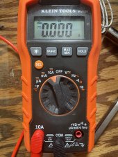
Yes, I attempted to do it with the 10a lead but for some reason it won’t read anything. I wasn’t sure if there wasn’t enough current to to pick up; however, I’m fairly certain the current isn’t the problem… likely user error lol. Let me know if you can spot the error… the pic was taken when touching the ring terminals of the charger. Thanks
5A5106F8-B29A-4AE6-9226-FAA26D6EECE8.jpeg
 
Yes, that is the correct way to read the 10a scale on your meter. The meter needs to be put in series, nor parallel to the circuit.
 
The Amps circuit on the meter is generally fused and may need to be replaced. If you forget and attempt to check voltage with the red wire in the 10A socket a dead short is created and will blow the fuse. I am not going to admit in public how many times I've done this over the years.
 
It's all to easy to blow the internal fuse when on the 10 amp range if accidently used in parallel. Almost everyone does this at some time with a similar meter.
It's easier to use a clamp meter, the low cost units from Amazon are excellent value, just make sure its suitable for DC current .Clamp meter
 
Last edited:
It's all to easy to blow the internal fuse when on the 10 amp range if accidently used in parallel. Almost everyone does this at some time with a similar meter.
It's easier to use a clamp meter, the low cost units from Amazon are excellent value, just make sure its suitable for DC current .Clamp meter
I was about to make a similar reply but decided to look up the manual for the meter to help describe the fix. The manual says there are no user-serviceable internal parts, so I have no idea if there is a fuse and if so, how hard it will be to swap out. (The meter I have has a fuse that is easy to change (Don't ask how I know :confused:). I could imagine a lower-end meter with the fuse soldered in or worse yet... no fuse at all. (Why would you need a fuse when you have all the circuitry that will blow?)

BTW: The description from the poster said: "the pic was taken when touching the ring terminals of the charger." The 10A power supply may or may not have blown something in the meter, but if the supply was hooked to the cells at the same time, there was definitely enough current available to blow an internal fuse.
 
I was about to make a similar reply but decided to look up the manual for the meter to help describe the fix. The manual says there are no user-serviceable internal parts, so I have no idea if there is a fuse and if so, how hard it will be to swap out. (The meter I have has a fuse that is easy to change (Don't ask how I know :confused:). I could imagine a lower-end meter with the fuse soldered in or worse yet... no fuse at all. (Why would you need a fuse when you have all the circuitry that will blow?)
It appears to be replaceable internally, but it's pretty inconvenient.
 
Thanks to everyone who is answering my newb questions. Currently, my battery is charging at the same rate on the charger, but the voltage, as read by the multimeter, is dipping. It rose to 3.372v before falling down to 3.368v. Is it normal for it to fall while charging?
 
Back
Top