diy solar

diy solar

Trailer Solar System - Avoiding Flames...

A disconnect has two studs, more opportunities to short out the battery.
I could see having disconnect first, but only in a configuration such that shorting to its terminals is virtually impossible.

When replacing a fuse, you would like neither terminal hot, so short by wrench handle isn't a problem. Disconnecting negative side of battery is one approach.

For grid AC wiring, of course a disconnect comes before fuse. Although, I could imagine a touch-safe fuse holder coming first.

For batteries, "MRBF" fuses bolted directly to battery terminal are available. Obviously, that is before any disconnect.
 
Where does this come come from?
Put the disconnect first so nothing is energized when the power is disconnected.
I stickin’ with rmaddy.
The trailer brakes should always be installed failsafe and shouldn’t be dependent on other systems.

But - just like an entrance/breaker panel where the main breaker is the safety before the panel bars distribute to the load breakers- the fuse should be capable of clearing the earliest available fault in the circuit.
 
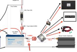
q: what is the black box in the top right corner?
q: Is the house power box a legacy dc distribution panel?
q: what is the pile of wire below the house power object?
 
I would not wire it like you have in the diagram. The ANL or Class-T fuse needs to be closest to the battery. I would wire it more like this (adding a bus bar):

battery positive -> main fuse (ANL or Class-T) -> positive bus bar

positive bus bar -> inverter cut off switch -> inverter fuse -> inverter

positive bus bar -> SCC breaker (or SCC cut off switch -> SCC fuse) -> SCC

And if you add the positive bus bar it might be nice to also have a negative bus bar. This way you aren't connecting multiple things directly to the battery terminal. Plus it makes adding a shunt simpler if you decide to do that later.
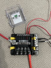
The saftey hub is essentially a busbar.
It has 1 un-fused positive position and 4 high current fused branch positions.
Unfortunately it only has 3 high current negative positions.
I suggest using it as the core of the system with a supplemental negative busbar.

I think its a neat solution for a smaller system.

I think those are gel batteries so a class-t fuse is not required but I do suggest one of these fuses in one of these holders.
 
Last edited:
Where does this come come from?

Put the disconnect first so nothing is energized when the power is disconnected.

A starter (not applicable here) motor can't be fuse so a disconnect can be used. The highest load I've pulled disconnects was probably around 3000A@36V.

Only thing that should bypass the disconnect is the trailer brakes. Which is protected with a fuse
Not really.
A fuse is needed directly at the battery rated for catastrophic failure protection.
 
  • Like
Reactions: Zil
q: what is the black box in the top right corner?
q: Is the house power box a legacy dc distribution panel?
q: what is the pile of wire below the house power object?
Hi. Thx for your questions.

q1: that is a facon 12v rv water tank heater as per will's video on warming batteries
q2: the house power was wired into the trailer before I received it. It is simply wired directly from the tongue box to the switches, 12v plugs (usb and cigarette), and led lights in the trailer. Not much draw from the house. Incidentally, the fridge stays in the 4runner and runs off a Yeti 500x
q3: that is a female cigarette plug for running the fridge (needed some wire length to get to the 4runner) when the yeti is charging off the solar.

I am all ears on suggestions as always! Thx again.
 
Code:
legend {
    {} { functional block }
    nnn|NNN| { busbar fused position where nnn is wire guage and NNN is fuse rating in amps
    nnn|UUU| { busbar un-fused position where nnn is wire guage
    <-> { bi-directional current flow }
    -> { uni-directional current flow }
    <- { uni-directional current flow }
    @ { back reference }
    dpst_switch { double pole single throw switch }
}
safety_hub {
    pos {
        002|UUU|<->disconnect_switch<->zcase_fuse<->battery.pos
        002|200|->inverter.pos
        006|100|<-solar_charge_controller.out.pos
        ???|???|->black_box.pos
        ???|???|->house_power.pos
        ???|???|->pile_of_wire.pos
        016|001|->shunt.pos
    }
    neg {
        002|UUU|<->shunt.neg.system
        002|UUU|<-inverter.neg
        006|UUU|->solar_charge_controller.out.neg
        ???|???|<-black_box.neg
        ???|???|<-house_power.neg
        ???|???|<-pile_of_wire.neg
    }
}
solar_charge_controller {
    in {
        pos<-dpst_switch<-panels.pos
        neg->dpst_switch->panels.neg
    }
    out {
        pos@
        neg@
    }
}
shunt {
    pos@
    neg {
        system@
        battery<->battery.neg
    }
}
 
Last edited:
Not really.
A fuse is needed directly at the battery rated for catastrophic failure protection.
Thx. As per above, there seems to be a growing consensus that the fuse comes before the disconnect (see attached). The wire there is 4AWG so based on Blue Sea's fuse chart, looks like a 150a fuse. I have a 150a ANL fuse already yet (above) seems like the recommendation is a class T. Also attached, the Safety Hub as it's currently mocked up - battery red coming in on the left, outgoing to inverter on bottom (MIDI fuse not installed yet as it has not arrived), and house and heater low amp showing on top and right. Sounds (as per above) that this could work instead of a bus bar. I hope that's the case although ... safety first!

Please point out any and all flaws in this summary. Thx again.
 

Attachments

  • IMG_8882.JPG
    IMG_8882.JPG
    354.2 KB · Views: 18
  • draft 2.jpg
    draft 2.jpg
    173.7 KB · Views: 19
These accept class t rated fuses also...
Yes some of them do. Thanks Supervstech.
The Siemens disconnect in the photo is 60 Amps, general duty.
One would need to upgrade to a 100 Amp disconnect to utilize the Class T Fuse adapter kit.
I wanted to clarify that before someone thought they could put a Class T Fuse in that particular box. ;)
 
12v plugs (usb and cigarette)
I would recommend either putting the USBs on a timer or at least a switch. I’ve seen them idle draw a lot (forget the watts) and get very hot on standby. Others are mW and only get warm while running. I’m not scared of fire but I am scared of burning stuff down. Yours could be fine but I haven’t seen consistency in the covidland models.

Either way: I don’t like to leave those things on unattended or for lengthy periods of time when they accumulate heat enough to be uncomfortable to the touch. Test ‘em. Check ‘em. Fuse them.
Thx much. I have the USB and cigarette plugs on a switch although they are not fused (other than the safety hub). I will correct that. Thx!
 
A disconnect has two studs, more opportunities to short out the battery.
I could see having disconnect first, but only in a configuration such that shorting to its terminals is virtually impossible.

When replacing a fuse, you would like neither terminal hot, so short by wrench handle isn't a problem. Disconnecting negative side of battery is one approach.

For grid AC wiring, of course a disconnect comes before fuse. Although, I could imagine a touch-safe fuse holder coming first.

For batteries, "MRBF" fuses bolted directly to battery terminal are available. Obviously, that is before any disconnect.
Thx. An MRBF fuse would definitely help with the space constraint issue I'm dealing with.
 
Looks like MRBF at 14V is good for 10,000A short circuit interrupting.
That may be sufficient for your batteries (especially with one fuse per battery.)
Do you have internal resistance spec for those cells? I would divide cell voltage e.g. 3.4V by IR to conservatively estimate max short circuit current.
The bigger cells people use for DIY I estimate 20kA, but yours could be under 10kA.

Thx. I cannot seem to find the IR for this battery but will keep looking (Renogy Smart Lithium Ion Phosphate) https://ca.renogy.com/renogy-smart-...MIqonujpq19QIVAg2tBh38rwDhEAQYASABEgKT0_D_BwE

I do like the space saving idea of a MRBF fuse. I believe I would need a 200a MRBF fuse but could be wrong. If this solution is workable, it would be good for my set up.

"Maximum Continuous Discharging Current: 100 A"
If fusing just for that, you would want a 125A fuse on each battery.
Depending on what surge you need, and time/current curve of fuse, larger could be appropriate.
And you don't want to blow them precharging capacitors! precharge circuit would be good.
Wire ampacity should be sufficient for fuse rating. Sum of two fuses after current from two batteries is paralleled.

I can't find mention of IR either.
Some BMS report calculations of IR.
I suspect you're OK with 10kA.
It is the 280 Ah cells with 0.17 milliohm measured IR where I come up with 20kA (maybe really less due to response of chemistry.)
I've tried calculating how cable resistance improves the situation. Don't add to resistance of a single cell, rather to 4x cell resistance, divided by 2 batteries in parallel, and calculate current with full battery voltage.
 
Not really.
A fuse is needed directly at the battery rated for catastrophic failure protection.

I have 4 banks in parallel that are protect from a catastrophic failure in any of the other banks with a 200A fuse.

The 400A main fuse is located after the disconnects. The ideal would be to combine both into a 400A switching breaker.

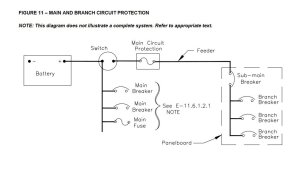
ABYC protection of the battery cable is to be a min. of 7" to 72" (depening cable protection) and a disconnect can be as close as practical.

11.6.1.2.2 A battery switch shall be mounted in a readily accessible location as close as practicable
to the battery.

Capture.JPG
 
Alloy. I thought the ABYC rule is catastrophic fuse not more than 7 inches from the battery terminal. There are a lot of points in that diagram where a random event could short the battery before the circuit protection.
 
"Maximum Continuous Discharging Current: 100 A"
If fusing just for that, you would want a 125A fuse on each battery.
Depending on what surge you need, and time/current curve of fuse, larger could be appropriate.
And you don't want to blow them precharging capacitors! precharge circuit would be good.
Wire ampacity should be sufficient for fuse rating. Sum of two fuses after current from two batteries is paralleled.

I can't find mention of IR either.
Some BMS report calculations of IR.
I suspect you're OK with 10kA.
It is the 280 Ah cells with 0.17 milliohm measured IR where I come up with 20kA (maybe really less due to response of chemistry.)
I've tried calculating how cable resistance improves the situation. Don't add to resistance of a single cell, rather to 4x cell resistance, divided by 2 batteries in parallel, and calculate current with full battery voltage.
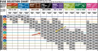
OK. Sounds good. Based on the attached chart from Blue Sea - I am looking to finalize my fuse selection. The wire in question is 4AWG. In the Blue Sea Safety Hub 150, I have planned a 150amp MIDI fuse as per the chart (red arrow). If I place a MRBF fuse at each positive terminal (batteries connected in parallel), would that be a 200amp fuse? (yellow arrow)as I am assuming that the fuse at the battery would be larger than the fuse in the Safety Hub (fuse block). I dont see a 175amp MRBF fuse from Blue Sea. Or, I suppose I could go 125amp at the Safety Hub and 150amp at the MRBF. Thoughts?

Everyone's assistance to think through this solution is amazing. I will post a final picture of the plan once finalized - maybe others can benefit from my learning.
 

Attachments

  • fuse selection.jpg
    fuse selection.jpg
    775.8 KB · Views: 7
Back
Top