diy solar

diy solar

Understanding MPP Solar charge settings for LifePO4 batteries

One other point . Like most chargers on the market today these things are made for lead acid and fudged to supposedly suit LFP.

They do not . LFP has no place or need of "absorption". It is Constant Current/Constant Voltage if you can get it then shut off when 3.4v is reached and you are done . If you have Constant Voltage set to 3.65v then the current will taper off as the plate voltage comes up to 3.4v and the current will be under 0.1C at that point. Just switch it off if you can.

Better to balance down below 3 volts when you know each cell is in the last 10% of its capacity. Its too easy to get it wrong and do damage top balancing.

I have a recent MPP HV2-5048 and it still has the same charging profile deficiency . maybe one day they might fix it or someone here design a fix for LFP.
 
Last edited:
I have a few MS5048's and I have the same issue. What I have done is I have put a contactor on the solar input side which is controlled by the SOC relay on a Victron BMV700. It works a charm but I have since discovered there is another solution. Some folks downunder in the AEVA forum have produced new firmware for some MPPs to make them more lithium friendly. The firmware, amongst other things, stops the nuisance going to float to early problem and it also stops the annoying under volt warning for the narrower lithium voltage spread.
Wow ... to the alternative firmware info. ... I wonder if anything like that exists for MPP LV2424. ... I am sure to go look search ... (eventually) for downunder in the AEVA forum to see what's up for alternative firmware updates. What would be important to me if I want to try an alternative source firmware update is having a copy of original firmware as backup, plus great references for success on alternatives. Thanks for interesting post.

added note: Got in quick search of AEVA forum at link below; ...seems like alternative firmware projects are limited to the bigger (than mine) and maybe newer 48v systems / still looks like interesting study arena:
 
Last edited:
I have a few MS5048's and I have the same issue. What I have done is I have put a contactor on the solar input side which is controlled by the SOC relay on a Victron BMV700. It works a charm but I have since discovered there is another solution. Some folks downunder in the AEVA forum have produced new firmware for some MPPs to make them more lithium friendly. The firmware, amongst other things, stops the nuisance going to float to early problem and it also stops the annoying under volt warning for the narrower lithium voltage spread.
Do you have a direct link to this conversation?
 
Okay so the Bulk charging time stuff did nothing for me, the MPP is leaving so much power out there. None of the settings seem to make any difference it just is not pulling enough power and pushing it to the batteries. Bulk or Float. I have Lithium so the voltage range for me I'm operating between is 48V-57V, I have useable and above and below but don't need it so rather maintain battery life. My solar will surge when my load is higher(microwave) or when a sudden burst of extra solar pops up like from behind a cloud. So do I need to flash a firmware change or something? This is the LV5048 with a 4kw solar array.


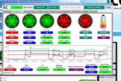
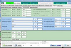
Capture2.JPGCapture33.JPG
 
Th
Don't tell people to do this . Its wrong and will damage their LFP cells. I'm not going to argue it with you . If you don't know why its wrong then research SEI layers. You are acting as a moderator . You need to have it right because most will be scared to argue with you.

No higher than 3.5 volts fellas and in practice 3.4v is a safer level and they are full at that if you look on a discharge graph.
You only go to 3.65v on the very first charge on cells you are sure are brand new.

Here is a graph produced by EVPower that reflects what I believe to be correct . It matches graphs I have produced during testing . Also its available on their website so see for yourself. I think the sellers draw theirs themselves to enhance sales.

You will notice there is nothing above 3.4volts.
This also points out the latent error in trying to estimate the SOC of a LFP cell . It can't accurately be done on a voltage basis . 3.2 volts could be anywhere on a 80% spread.

Why would you use discharge curves when talking about charging?
 
Th
Why would you use discharge curves when talking about charging?
If you go to their site the discharge is the only graph they have publicly available . As you know the charge graphs are only slightly higher on start . The point of that graph is to show the flatness of the curve in relation to voltage of the cells and as I said its the one graph I have seen produced locally (ie outside of China) that corresponds to my own results so I believe it is factual and not someones stylised drawing.
The discharge graph also shows what I have found in practice that they are full at 3.4v if you look on the discharge graph. Turn the charger OFF and the voltage will immediately drop.
 
Last edited:
I haven't used the new firmware yet because I used alternative solutions to the MPP shortcomings. If I had know before I implemented my solutions I would definitely have had a fo at the new firmware.
 
So some extra testing with my LV5048, the Float number seems to do effectively nothing when it comes to charging, the Bulk number seems to control everything. However I'm still finding that it leaves some solar power out but not much 200-300 watts from max output like 10%
 
If you go to their site the discharge is the only graph they have publicly available . As you know the charge graphs are only slightly higher on start . The point of that graph is to show the flatness of the curve in relation to voltage of the cells and as I said its the one graph I have seen produced locally (ie outside of China) that corresponds to my own results so I believe it is factual and not someones stylised drawing.
The discharge graph also shows what I have found in practice that they are full at 3.4v if you look on the discharge graph. Turn the charger OFF and the voltage will immediately drop.

Just because that's the only data that's publicly available doesn't mean it's the data you should use.

Is it your position that a 12V lead-acid battery should not be charged above 12.7V because they are "full" there? I hope not. They're not full there, not even close, unless they've recently been charged to 14.XV and held there for hours.

LFP is highly similar. It's charging voltage is higher than its working/resting voltage.

I'm going to put cell manufacturer data over "their site." Most indicate a charge voltage of 3.55 to 3.65V/cell at a tail current of 0.05C. That means a short absorption phase is required to attain full charge. Those that say LFP does not need an absorption phase are making recommendations inconsistent with cell manufacturers.

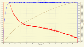
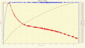
They are absolutely not full at 3.4V in all cases. You're omitting tail current as a charge termination criteria. Here's an example of a CALB cell charged to 3.4V @ 0.3C:

1614712650296.png

It was at less that 20% SoC when 3.4V was hit. It had to be held there for about 6 hours to get it to charge to about 95% with a tail current of 0.03C.

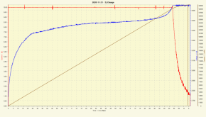
Exact same cell charged to 3.65V @ 0.3C:

1614712911141.png

It required a short absorption phase to attain full charge.

Saying cells are fully charged at 3.4V is not accurate without qualifications, and you can never actually get fully charged at 3.4V, but you can get very nearly there.
 
Last edited:
Just because that's the only data that's publicly available doesn't mean it's the data you should use.

Is it your position that a 12V lead-acid battery should not be charged above 12.7V because they are "full" there? I hope not. They're not full there, not even close, unless they've recently been charged to 14.XV and held there for hours.

LFP is highly similar. It's charging voltage

I'm going to put cell manufacturer data over "their site." Most indicate a charge voltage of 3.55 to 3.65V/cell at a tail current of 0.05C. That means a short absorption phase is required to attain full charge. Those that say LFP does not need an absorption phase are making recommendations inconsistent with cell manufacturers.

They are absolutely not full at 3.4V in all cases. You're omitting tail current as a charge termination criteria. Here's an example of a CALB cell charged to 3.4V @ 0.3C:

View attachment 39216

It was at less that 20% SoC when 3.4V was hit. It had to be held there for about 6 hours to get it to charge to about 95% with a tail current of 0.03C.

Exact same cell charged to 3.65V @ 0.3C:

View attachment 39217

It required a short absorption phase to attain full charge.

Saying cells are fully charged at 3.4V is not accurate without qualifications, and you can never actually get fully charged at 3.4V, but you can get very nearly there.
Great info in those graphs
 
As I said snoobler . I'm not going to argue it with you here . You have more to learn and I notice how you creep negativity into your posts with references to non existent material . I have seen you do that before . Where did lead acid come into it . LFP needs no absorbtion and is completely different to Lead and is fully charged ,after first charge ,at 3.4 volts plate voltage. Convenient that you happened to do a graph on 21/11/20 at 3.4v ,highly suspect.

Again as I said you need to study the SEI layer because what you advise is damaging others' batteries .
Clearly you are just looking for a gunfight when you have the only gun . Not getting into that Chum . Common saying in Yorkshire ,"None so deaf as those who do not want to hear".


1614712650296.png
 
Last edited:
My surplus Byd batts will absorb 3-4 hrs at 3.4v per cell, they will accept an additional 10% charge once they hit the 3.4v per cell at absorption.
 
As I said snoobler . I'm not going to argue it with you here . You have more to learn and I notice how you creep negativity into your posts with references to non existent material . I have seen you do that before . Where did lead acid come into it . LFP needs no absorbtion and is completely different to Lead and is fully charged ,after first charge ,at 3.4 volts plate voltage. Convenient that you happened to do a graph on 21/11/20 at 3.4v ,highly suspect.

Again as I said you need to study the SEI layer because what you advise is damaging others' batteries .

I agree I have more to learn, but not about the specifics we're discussing.

Please identify a post referring to "non existent material."

Lead came into it because the charge profile of lead and LFP are similar requiring bulk (constant current) and absorption (constant voltage) phases depending on charge current. The 3.4V charge has a multi-hour absorption phase in order to get to nearly fully charged.

Please refer to the Eve data sheet, section 4.2:


Standard full charge is 0.5C to 3.65 and a cut-off of 0.05C. The region where it's charging at 3.65V and tapering from 0.5C (140A) to 0.05C (14A) is exactly like a lead acid absorption phase and tail current in concept, although typically of much shorter duration than lead.

There is nothing convenient about it. It simply happened. There is no conspiracy. I took some CALB cells that had been in storage for a year, and I wanted to test them. I don't just rely on publicly available information. I'll often generate my own test data to answer a question or to establish correlation with published data.

I have posted these charts before:

12/28/2020:

1/15/2021:
 
Which mpp solar do you have?
I have 2x PIP-5048MG with 3x Pylontech US3000. I'm very happy with my setup but if I bought today it would be one of the newer ones like the PIP-MAX or one that has 0ms transfer time with lithium BMS connection support.
 
I have 2x PIP-5048MG with 3x Pylontech US3000. I'm very happy with my setup but if I bought today it would be one of the newer ones like the PIP-MAX or one that has 0ms transfer time with lithium BMS connection support.
I bought Solar Assistant, but my pi is too old. Tomorrow the new one will be here. I hope my LV6548 works with it.
 
Back
Top