diy solar

diy solar

Unexplained Parasitic Amp Loss

NowARamGuy

New Member
Joined
Jan 20, 2022
Messages
8
Hello. I am new to DIY solar forum. This is my first question. Through hours (months actually) of searching, reading and youtube videos, I have finally built my system and it appears functioning, but I have a parasitic -2.8 amp loss in my system that I just cannot seem to account for. I am able to run a vacuum cleaner and microwave off the Inverter and when I plug back into shore power, the Charger kicks in and tops off the batteries as expected. Once I achieve Float status, the Charger is outputting 13.75V, however the battery is being drained.

I am aware of the DC power consumables such as the fridge control panel, Carbon Monoxide detector, shunt and the BMS(s), etc. As I turn the components off, I continue to see -2.8A at the shunt. I have gone through my settings starting with the BMS(s), Shunt and Multiplex-II and have begun to reach out to the specific help lines for those components. In the interim I thought I would reach out here and see if a discussion with those who know might have a suggestion.

I was under the impression that once the Charger reached the Float state, it would be presenting enough volts/amps to power the DC consumables as well as provide power for the BMS balance operation. That doesn't appear to be the case and I am running out of things to test. Which reminds me, I have a lot of test data that I can supply, but I thought I would hold that back until asked.

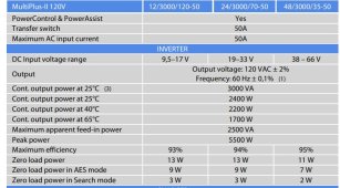
Here's my system: Victron Multiplus-II 3000 120-50 2x120V, Victron BMV-712 w/shunt, Victron Lynx Distribution, 2 battery pack consisting of EVE 280Ah cells with a 120A 12V 4S Overkill BMS.

I am open to any and all criticism...that will only make my system better.

Thanks in advance,
Paul


View attachment 94514View attachment 94515View attachment 94516View attachment 94517View attachment 94518
 
How long did you wait after float was achieved? Since float voltage is lower than absorb voltage, I would expect some energy to come from the battery until the battery voltage matched.

Also, your cell 4 voltage is very high. Did you top balance your cells? It looks like you didn't; you're way out of balance. I think the fact that the Charging "switch" in the app is off means the BMS has disabled charging, presumably due to cell 4 being high. That may also account for what you're seeing.
 
Battery voltage drops after charging stops. I'm guessing here but could that be some of what you are seeing?

Nice setup you have there.
Here are a few things which are a bit off topic & don't require a response.
Could your batteries be compressed a bit much? I don't usually see plywood bending.
Is the switch, circled in red, meant to be used while current is flowing through? Most of those switches are not meant to be switched under load.
The cardboard box made me laugh. ParasitePic2.PNG
 
How long did you wait after float was achieved? Since float voltage is lower than absorb voltage, I would expect some energy to come from the battery until the battery voltage matched.

Also, your cell 4 voltage is very high. Did you top balance your cells? It looks like you didn't; you're way out of balance. I think the fact that the Charging "switch" in the app is off means the BMS has disabled charging, presumably due to cell 4 being high. That may also account for what you're seeing.
Thanks for the response. I am preparing to re-do the top balance. They have been sitting for about 7 weeks and I've just been procrastinating. There are a couple of clean up items I need to do, which involves pulling my battery box. RE: charging "switch"... That's something else to check. Thanks.
 
Battery voltage drops after charging stops. I'm guessing here but could that be some of what you are seeing?

Nice setup you have there.
Here are a few things which are a bit off topic & don't require a response.
Could your batteries be compressed a bit much? I don't usually see plywood bending.
Is the switch, circled in red, meant to be used while current is flowing through? Most of those switches are not meant to be switched under load.
The cardboard box made me laugh. View attachment 94535
My threaded rods were a bit short (giggles only please) which caused the bowing. I've seen springs to compensate for the expansion/contraction as the cells charge/discharge. I'll need to purchase more threaded rod and add the springs. That will take care of the compression topic. I'll be top-balancing the cells once again and make the modifications.

RE: Switch; I assume that the switch should always be "on" to allow the batteries to be charged either by the Multiplus-II or the solar panels. Is this an incorrect assumption? I did not even consider the switch to be toggled under load. That would be, as they say, "not good".

Thanks for the suggestions.

P.S. RE: Box... I needed someplace to hold 10 meters of phone cord! Why not the box it came in? ;)
 
How long did you wait after float was achieved? Since float voltage is lower than absorb voltage, I would expect some energy to come from the battery until the battery voltage matched.

Also, your cell 4 voltage is very high. Did you top balance your cells? It looks like you didn't; you're way out of balance. I think the fact that the Charging "switch" in the app is off means the BMS has disabled charging, presumably due to cell 4 being high. That may also account for what you're seeing.
I've double-checked the settings on the Multiplus-II:

Enabled Chargerchecked
Weak AC Inputchecked
Battery TypeLitihum
Charge curveFixed
Absorption Voltage14.6 V
Float Voltage13.8V
Charge Current50 AAlthough the system can hand 100 A
Repeat Absorption Time0.25 Hr
Repeat Absorption Interval7 Days
Absorption Time1 Hr

As you've probably seen from other messages, I will be top-balancing the cells this weekend.

Thanks for your comments.
 
I take it this is a mobile ap - rv or trailer or something since you mention a CO alarm and 'shorepower'.

2.8A is quit a bit...I searched for a half an amp, and found it with my outdoor AM/FM radio. When power is dico'd and restored the radio comes on by default. That was my half amp drain. The propane sniffer is a tenth of an amp - and that's what I have now when everything is turned off.

A shunt will also use a tenth of an amp or so.

You could have a cargo bay light left on, or a auto-closet light, or something like that. A car radio left on standby, or a tuner, or any other electric or electronic gadget.
 
Once you get the battery situation squared away, you can start pulling fuses / throwing breakers in your 12v fuse box to see where the power is going. It's also possible to measure for voltage across each side of a blade fuse - if you have anything other than 0 volts, then current is flowing through that fuse. There are small exposed areas at the top/head of the fuse for making such a measurement.
 
The battery is draining while plugged into shore. Generally the battery should be net-0 while floating on shore power. Hence my previous comments.
 
UPDATE: As suggested and as I committed to, I have top balanced and tested my batteries over the weekend. It took me all weekend to do this. Testing them with the BMS showed that they are functioning much better, although one BMS is having trouble performing the top balance after a significant drain. (I ran the A/C for about 15 minutes to get the battery cells below to 3.2V.) Then let them rest for 9 holes of golf. I then started the charge cycle. One battery bank came up fine (delta between cells is: 0.013V) and the BMS is actively charging/discharging, however the other BMS is having issues balancing the cells (delta between cells is 0.129V. I am of the mindset that it may be the BMS itself (different firmware version???)

The overall 40W battery parasitic drain still exists. I am about to go through the process that cinergi suggests isolating the circuits. I'll start by pulling the AC out of the equation and focusing on the DC side only. I know their are several components as the first targets: DC circuit board in the fridge, Radio, Antenna amplifier, CO2 detector, etc. ending with the last component the Shunt (spec says should be 1mA @ 12V). The issue may also be the shunt itself. We'll see.

I will report back once I get that data set. Oh! Thanks cinergi for the suggestion about measuring current across the fuse terminals. That would make this exercise so much faster!

I truly want to thank everyone for their suggestions. I know, in the end, this is going to be something simple (or at least explainable).
 
Be aware: Not all dc devices are wired through the dc panel and our parasitic draw is still there when the main fuses are pulled out of the dc panel (it's related to our gas detector and 'sleeping' circuits that are waiting for some kind of remote for input). It's hard to imagine what could be pulling 40 watts, but I'd still suggest you start by pulling the mains to see if the loss still happening.
 
Problem Solved!
I must have toasted my shunt during my battery build out. The replacement shunt is now showing 0.00 Amps being drawn and the batteries are behaving as they should be. Thanks everyone for helping me figure this out. All of your suggestions were very helpful and I've learned a ton.
 
Back
Top