The short version - I am seeing cell(s) triggering high and low voltage disconnects, which makes me suspect capacity issues, but it's not always the same cell which doesn't make a lot of sense... read on!
Setup
- JK 150a BMS (w/ 2a active balancing on from day 1)
- Heltec stand alone 5a Active Balancer
- MPP7248
- ETC 277ah cells.
- Pack has been in service for 14-16mths
- M4 studs into terminals, copper grease on balance lead connections, washers between things.
- Pack is setup in an 8x2 layout and is strapped with ratchet straps to provide some light compression and uses boards at each end to keep the pressure off the cells directly.
- Pack lives in an enclosure with the other gear, there is a filtered fan (temp controlled) and highest temp I've seen in the cabinet is high 30s
- Temp probes on the BMS appear to be accurate vs the thermocouple on my Fluke 325, the enclosure has never gotten close to zero.
- The pack was top balanced with a DC supply set at 3.65v for 2 weeks before it went in to service. This included periods of letting the pack rest/settle.
- HVD/LVD was previously set at 3.6v/3v respectively, but I've had to widen those out recently due to cell behavior above.
- Bulk charge/float charge settings were always set in the high 54/low 55v range (depending on the season/available sunlight) so the HVD never came in to effect really.
- Max charge from the inverter is 80a. Max discharge was set to 120a with a breaker at 125a - no smart shunts or anything like that in this system.
- Cells are connected by 2x bus bars per connection except between cell 8 and 9.
Background/Issue in detail
- I have had some previous issues with a cell here or there hitting High OR Low voltage disconnect previously, but rarely and there's always some differences between cells. I have moved cells around to confirm it was the cell and not the BMS which it always appeared to be. If a cell was hitting HVD it was never hitting LVD also.
- 6mths or so ago the BMS failed, it would not read 3-4 different cells and it was sent back to JK for repair, after issues with customs and freight times it easily took that long again to get it back, it's only been back in service for a month or so. About 2mths in to that time frame I bought the Heltec 5a balancer and got it running for some safety - note you cannot see anything from the balancer directly but you can measure current on the leads and see it working. It seemed happy enough moving small amounts of current around as the operation was explained as it will move more current in relation to cell differences, bigger the difference the harder it will work up to 5a. I've never seen it moving more than a few amps in/out of a cell under load in the same way I have not seen the JK BMS move more than 1-1.4a vs the 2a rating.
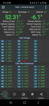
- After putting the BMS back on and being able to see all the cell values at a glance it was obvious things had changed, at rest things are fine and even but under charge/discharge of around 2kw (40a or so) you start to see cell 9 and 16 in particular, but sometimes cell 5 hitting HVD AND LVD depending on whether it's charging or discharging at the time, previously I could very easily pull 4-5kw from the pack with minimal differences. Sometimes it'll be only 1, sometimes 2, sometimes all of them doing this.
- We're talking seeing a cell hitting 3.7-3.8v when the rest are at 3.3-3.4v while charging and plenty of current still coming in so we're not near the top of the pack capacity yet. Similarly, down as low as 2.6 - 2.7 under load but then bouncing back to even with the rest at say 3.2 to 3.3 when the load is removed.
- I have tested with my Fluke and it does show a good 0.1 - 0.2v difference during these times, the display does not update fast enough or with enough decimals to see more than that so it does appear there's some truth to what the BMS is saying - though the Fluke never shows as high or as low.
- I had both balancers running, but have turned off the BMS balancer for now in case they are fighting each other, the problem is still evident with just 1.
- Cell 9 is the first in the second row of 8 cells and is connected via a heavy guage wire as the buss bars could not reach.
- Cell 16 is the main battery positive.
- Cell wire resistance values move around quite a bit if the BMS is restarted (the only time it will calculate them). Problem cells pretty much always have higher resistance values (internal resistance issues?) look at cell 16 in the below. When the pack was first commissioned all values were low .1xx and pretty even, they've gotten less even and higher since then.
- I note the pack has shifted a little, as in it is not a perfect rectangle anymore, I'm unsure if this is due to strapping being too tight/loose or the way force is applied in the corners as it wraps around.
- I am yet to move any of these cells around and had considered bringing the whole thing inside and doing a fresh top balance, but that's a bit of work and a bit of time back on the grid system plus I can't see how that would help if it's hitting high and low voltage disconnects.
Is it as simple as a capacity issue? Issue with having had 2 balancers on? Or do I bring it top balance put it back and leave balancers off and see what happens? Are ETC cells just shit and this is what I should expect?
All assistance welcome thanks.


Setup
- JK 150a BMS (w/ 2a active balancing on from day 1)
- Heltec stand alone 5a Active Balancer
- MPP7248
- ETC 277ah cells.
- Pack has been in service for 14-16mths
- M4 studs into terminals, copper grease on balance lead connections, washers between things.
- Pack is setup in an 8x2 layout and is strapped with ratchet straps to provide some light compression and uses boards at each end to keep the pressure off the cells directly.
- Pack lives in an enclosure with the other gear, there is a filtered fan (temp controlled) and highest temp I've seen in the cabinet is high 30s
- Temp probes on the BMS appear to be accurate vs the thermocouple on my Fluke 325, the enclosure has never gotten close to zero.
- The pack was top balanced with a DC supply set at 3.65v for 2 weeks before it went in to service. This included periods of letting the pack rest/settle.
- HVD/LVD was previously set at 3.6v/3v respectively, but I've had to widen those out recently due to cell behavior above.
- Bulk charge/float charge settings were always set in the high 54/low 55v range (depending on the season/available sunlight) so the HVD never came in to effect really.
- Max charge from the inverter is 80a. Max discharge was set to 120a with a breaker at 125a - no smart shunts or anything like that in this system.
- Cells are connected by 2x bus bars per connection except between cell 8 and 9.
Background/Issue in detail
- I have had some previous issues with a cell here or there hitting High OR Low voltage disconnect previously, but rarely and there's always some differences between cells. I have moved cells around to confirm it was the cell and not the BMS which it always appeared to be. If a cell was hitting HVD it was never hitting LVD also.
- 6mths or so ago the BMS failed, it would not read 3-4 different cells and it was sent back to JK for repair, after issues with customs and freight times it easily took that long again to get it back, it's only been back in service for a month or so. About 2mths in to that time frame I bought the Heltec 5a balancer and got it running for some safety - note you cannot see anything from the balancer directly but you can measure current on the leads and see it working. It seemed happy enough moving small amounts of current around as the operation was explained as it will move more current in relation to cell differences, bigger the difference the harder it will work up to 5a. I've never seen it moving more than a few amps in/out of a cell under load in the same way I have not seen the JK BMS move more than 1-1.4a vs the 2a rating.
- After putting the BMS back on and being able to see all the cell values at a glance it was obvious things had changed, at rest things are fine and even but under charge/discharge of around 2kw (40a or so) you start to see cell 9 and 16 in particular, but sometimes cell 5 hitting HVD AND LVD depending on whether it's charging or discharging at the time, previously I could very easily pull 4-5kw from the pack with minimal differences. Sometimes it'll be only 1, sometimes 2, sometimes all of them doing this.
- We're talking seeing a cell hitting 3.7-3.8v when the rest are at 3.3-3.4v while charging and plenty of current still coming in so we're not near the top of the pack capacity yet. Similarly, down as low as 2.6 - 2.7 under load but then bouncing back to even with the rest at say 3.2 to 3.3 when the load is removed.
- I have tested with my Fluke and it does show a good 0.1 - 0.2v difference during these times, the display does not update fast enough or with enough decimals to see more than that so it does appear there's some truth to what the BMS is saying - though the Fluke never shows as high or as low.
- I had both balancers running, but have turned off the BMS balancer for now in case they are fighting each other, the problem is still evident with just 1.
- Cell 9 is the first in the second row of 8 cells and is connected via a heavy guage wire as the buss bars could not reach.
- Cell 16 is the main battery positive.
- Cell wire resistance values move around quite a bit if the BMS is restarted (the only time it will calculate them). Problem cells pretty much always have higher resistance values (internal resistance issues?) look at cell 16 in the below. When the pack was first commissioned all values were low .1xx and pretty even, they've gotten less even and higher since then.
- I note the pack has shifted a little, as in it is not a perfect rectangle anymore, I'm unsure if this is due to strapping being too tight/loose or the way force is applied in the corners as it wraps around.
- I am yet to move any of these cells around and had considered bringing the whole thing inside and doing a fresh top balance, but that's a bit of work and a bit of time back on the grid system plus I can't see how that would help if it's hitting high and low voltage disconnects.
Is it as simple as a capacity issue? Issue with having had 2 balancers on? Or do I bring it top balance put it back and leave balancers off and see what happens? Are ETC cells just shit and this is what I should expect?
All assistance welcome thanks.
Last edited: