diy solar

diy solar

Upgraded motorhome set up 600w with AGM, thoughts please ?

MickyBoyMH

New Member
Joined
Apr 5, 2022
Messages
12
Hi all,

I'm upgrading the system on my motorhome as the current inherited system is old and not very effective (120w single panel with 20A cheapo nastio controller and 100Ah batteries)
After lots of reading and weighing up the pros/cons, I've gone with (and already purchased):

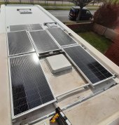
6 x 100w mono panels, in series (total max Voc of 129.6V and Isc of 6.11A)
2 x 180Ah AGM batteries in parallel (I'm waiting on specification data from supplier for parameters)
Epever Tracer 6415AN 60 Amp controller
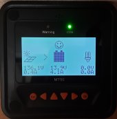
Epever MT50 Monitor
1000w PSW inverter
4mm2 solar cable - from array to controller

So my questions are:
1. As the array will be in series with Current remaining constant @6.11A am ok with a 10A breaker between the array and the controller?
2. What kind of current would I expect from the controller to the batteries (to determine cable size).
3. Considering question #2, what size rated breaker and fuse would I need between the batteries and controller?
4. I was intending to join the two batteries in parallel with 25mm2 links. Is this size sufficient?
5. Because of the parallel configuration of batteries being 12V/360Ah, in the Epever parameter settings, do I set the battery size as 360Ah or 180Ah. I've read that I'll need to set it up under 'User' settings as it won't recognise an AGM.

Thank you!

1. Likely. The panels have a maximum fuse rating on their label. Use that.
2. 600W/12V = 50A.
3. 1.25X the wire's rating.
4. Marginal. 1000W/12V/.85 = 98A
5. Series: Voltage adds, capacity/current unchanged. Parallel: voltage unchanged, capacity/current adds.

USER is typically best as you can program the MPPT for your specific battery.

Something to consider: partial shading is an issue on RV roofs. You might want to consider 3S2P or 2S3P array configurations for a little more shading tolerance.
 
I would go 20 Amp breaker for solar. You can do 3 series 2 Parallels for Redundancy and shading protection since you are 12v not 24v.

You would only have about 180ah for that bank, is that enough for you? What load demands do you have, Furnace kills them.
I went diesel heater for my Van. It uses 1 Amp after a 5 min turn on cycle. pushes WAY more heat and cheaper than rv furnace.

Do you have Temp protection for your MMPT? You need one for AGMs.

Do 2x inverter sizing for your MAX Sizing. ie if only 1000watts, get a 2000/4000peak inverter.
Its better to have an oversized inverter instead of really demanding 99% of your inverter. Larger Inverters have better cooling and heatsinks, terminals (for sizing of cable)

You will BUlk charge at 14.4V or 14.8V so that is 41 amps.
A 60 Amp Breaker Will Protect you.

You also need breaker from MMPT to Bank.

I was going to go the "economy" route for chargers, however the bonuses, bluetooth wifi etc of Victron is worth the investment. also the upgradability and connection of all the devices.
I love being able to just open an app to see what im using when something is turned on, time left etc.

My system.
1 24-100ah Amphere time 100amp draw.
2x- 300 solar series mounted - 1x 300 solar if needed.
150x35 Victron 24V. Victron smart BMV, Aims 1500/3000 Pure sine inverter 24v INverter. 24/12v 30AMP Buck Converter. 12v 50AH AGM, Backup. 8Amp 12v Charger.

Also, 12V AGM Batteries. at 12.2V You basically should stop using it.
12.8- 100%, 12.5 - 90%, 12.32 70%, 12.2 60%, 12.06 50% (out of power).
Get a Voltage Guage, Meter for cigarette etc. RV Build in Color Meters are useless.

Charged voltage for 12V RV AGMs is 30min with NO LOADs and then check.
Wet/AGMs - you will have voltage sag with a load connected.
Gauge-Chart[1].jpgState-of-Charge-Chart-Typical-Internet[1].jpg
 
Last edited:
1. Likely. The panels have a maximum fuse rating on their label. Use that.
2. 600W/12V = 50A.
3. 1.25X the wire's rating.
4. Marginal. 1000W/12V/.85 = 98A
5. Series: Voltage adds, capacity/current unchanged. Parallel: voltage unchanged, capacity/current adds.

USER is typically best as you can program the MPPT for your specific battery.

Something to consider: partial shading is an issue on RV roofs. You might want to consider 3S2P or 2S3P array configurations for a little more
 
5. Because of the parallel configuration of batteries being 12V/360Ah, in the Epever parameter settings, do I set the battery size as 360Ah or 180Ah. I've read that I'll need to set it up under 'User' settings as it won't recognise an AGM.

You can use the GEL setting, unless your depth of discharge requires a longer absorption duration.

battery-absorption-tmes.png
 
2. What kind of current would I expect from the controller to the batteries (to determine cable size).
3. Considering question #2, what size rated breaker and fuse would I need between the batteries and controller?
You have a 60A SCC so you should wire for that. Your planned PV may only result in 50A but it's better to wire for the hardware's potential. You might add another couple of panels in the future to make full use of the 60A charge current potential and you don't want to have to upgrade the wiring and fuse. Use 16mm² wire and a 75A fuse between the SCC and battery/bus bars.

4. I was intending to join the two batteries in parallel with 25mm2 links. Is this size sufficient?
Barely. 35mm² would run cooler.

5. Because of the parallel configuration of batteries being 12V/360Ah, in the Epever parameter settings, do I set the battery size as 360Ah or 180Ah. I've read that I'll need to set it up under 'User' settings as it won't recognise an AGM.
As you stated, the two parallel batteries will be 12V 360Ah so set the battery size to 360Ah.

You would only have about 180ah for that bank
The OP has 2 180Ah batteries in parallel so that's 360Ah, not 180Ah.
 
Thanks for feedback. In response:

1. I've not got panels (due tomorrow) but I have seen the label and no fuse info.... might be in a data sheet? but using ohms law suggests impossible to generate greater than the stated 6.21A and the cables at 4mm/12awg are well protected +30A, is 20A over kill for the breaker? What circumstance would generate +20A from a 6A system?
2. Ok, got it. Ohms again. W/V=I ? Given that I'll probably a lot of the time generate actual power less than 600w, the current goes down as power does, so while I'll may see peaks of 50-60A at best, the average will be less. But, I must of course prepare for the highest. As I do have some excess 25mm/4awg I might as well use it from the controller to the batteries, the length is about 3-4 metres so it'll help with the V drop.
3. A 63A breaker seems the right fit too.
4. 1000W/12V/.85..... where do you get the 1000w & .85 from?
5. So, in parallel I effectively have a 360Ah battery. How does the controller know? Do I set battery size as 360Ah in settings to trick it?

My load demands aren't heavy for the inverter, maybe upsize later in year.
Don't have heating at the moment (gas heater removed) but I will be fitting a diesel one this summer ready for next winter.
The old bank was only 150Ah useable so at 180Ah I've an increasen, maybe I'll be lucky with the deep cycles and get more than 50%?
I've got the temperature monitoring with the rs485 connection.

All fun n games ⚡
 
3. A 63A breaker seems the right fit too.
Not for a 60A SCC. The typical approach is 125% of the load. Hence a 75A fuse is appropriate for a 60A load. You will likely get away with a 63A breaker since you won't ever actually reach 60A with your planned solar array. But again, if you wire/fuse for the hardware, 63A is marginal.

4. 1000W/12V/.85..... where do you get the 1000w & .85 from?
Your inverter is 1000W (1kW). The 0.85 represents the (roughly) 85% efficiency of the inverter. 1000W at the inverter is 1000 / 85% = 1176W needed at the battery.

5. So, in parallel I effectively have a 360Ah battery. How does the controller know? Do I set battery size as 360Ah in settings to trick it?
The controller doesn't need to know the battery's capacity.
 
Thanks also for the comments just now, valuable opinions.... I'm taking it all in ?.

What about doubling up the 25mm? I've read that in some (uncommon) electric installations doubling is allowed to share the load.
 
Last edited:
What about doubling up the 25mm? I've read that in some (uncommon) electric installations doubling is allowed to state the load.
Doubling it where? You would only double 25mm² if you needed 50mm² and you didn't have any.
 
Not for a 60A SCC. The typical approach is 125% of the load. Hence a 75A fuse is appropriate for a 60A load. You will likely get away with a 63A breaker since you won't ever actually reach 60A with your planned solar array. But again, if you wire/fuse for the hardware, 63A is marginal.
Do I fuse and breaker or one or the other (assuming sized correctly)
 
Doubling it where? You would only double 25mm² if you needed 50mm² and you didn't have any.
Right now I don't have 50mm but if 25mm is not enough for the load then doubling up would be more than I needed for the load with greater margin too?
 
Right now I don't have 50mm but if 25mm is not enough for the load then doubling up would be more than I needed for the load with greater margin too?
I ask again. Doubling up where? You don't seem to need 50mm² anywhere. Doubling up wire isn't ideal. Then you need two fuses, one for each wire, totaling the size of a single fuse if you only used one wire. If one fails then the other will fail quickly too costing twice as much to replace.

Do I fuse and breaker or one or the other (assuming sized correctly)
Normally it's one or the other, not both. A fuse is usually better but in some cases using a breaker allows it to double as a disconnect switch.
 
Your inverter is 1000W (1kW). The 0.85 represents the (roughly) 85% efficiency of the inverter. 1000W at the inverter is 1000 / 85% = 1176W needed at the battery.
Ah, I see. So if inverter was at max. draw it'd be pulling 98A.
 
I ask again. Doubling up where? You don't seem to need 50mm² anywhere. Doubling up wire isn't ideal. Then you need two fuses, one for each wire, totaling the size of a single fuse if you only used one wire. If one fails then the other will fail quickly too costing twice as much to replace.
Sorry if it wasn't clear, the link cables joining the batteries in parallel. I have 25mm handy but nothing bigger to hand, unless purchased.
 
Sorry if it wasn't clear, the link cables joining the batteries in parallel. I have 25mm handy but nothing bigger to hand, unless purchased.
If you keep the total length of the battery wires as short as you can then single 25mm² wires will work fine as long as it is high quality marine grade pure copper stranded wire rated to 105ºC.
 
Back
Top