diy solar

diy solar

using wire length and awg as charging and discharging limiter

byteharmony

Sunny side up please.
Joined
Jul 29, 2022
Messages
233
Location
Milwaukee
Question: Is there any reason this is a bad idea?

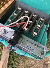
Inspired by this guys recycled AC Panel:

Does anyone have any experience with limiting charge current and discharge current by wire gauge and length?

An example of this is using 14 AWG wire to directly connect two different LIFEPO4 batteries in parallel that are far apart.

For example:
14 awg THHN
53v max charged battery (Trophy Battery)
100 foot distance
15 AMPS max breaker
9.33 volt drop on breaker flip
43.67 volts at discharged battery
15 amps starts flowing and it drops to 0 once they are top balanced.

The magic is, should I lose power or choose to go off grid for time of use cost savings, or need power capacity beyond my 100 AMP grid limit, the flow would go backwards and the far away battery would supply current to the primary battery increasing it's capacity, then switch back once the load drops to charging. No extra cost for fancy electronics to do this, just distance and physics.

Drop the distance to 30 feet and the max voltage drop is only 2.8v meaning i couldn't connect the batteries until the remote battery was at least 50.2 volts and even then their is an added risk of over drawing if I don't limit my consumption and charge with the sol ark programming. Still the breaker is a backup protection.

Why do this?

Where my Sol Ark will be it's easy to fit 1 Trophy rack battery and my DIY 18650 power wall.

However my planned 48v lawn tractor and 48v pontoon boat will also have 48v Trophies in them in the summer. I got to thinking, instead of using 48v AC 120v chargers, I'd just run a longer 48v feed to them. With this approach I can also connect my 120V 2500 Watt gas generator stored by my tractor up to a 48v charger and keep my whole house running in the vent of a power outage and my power consumption out draws my capacity. I wouldn't have to move or wire up much of anything.

In the fall / winter I can pull the 2 large trophy batteries into the house and place them in my existing 40 U server rack (I know it's weird but I have a lot of servers) and then run a power wire to that rack so that it can feed the primary trophy batter and the space works out for me perfectly. The primary battery can act as a large capacitor to some degree.

Worst case I melt a wire, cause a short and my breaker in the distribution panel at 15 amps trips. Wires are all in 1/2 emt so fire is prevented.

Labels on conduit of course.

Each situation would need smart thinking for battery size, wire size and distance. But it seems smart in theory. Better for all batteries concerned and me.
 
He said Sol-Ark shut down on grid power. Being a pass through, how is that possible?
 
It's totally fine, if Y'all don't mind your stuff catching on fire every now and then.....??

Thanks for the feedback, could you shed some light on where you'd see the fire starting?

This comment from @Vigo touches on exactly the idea I'm thinking of, use the NEC documented resistance of the wire and load capacity as a resister to predict and control voltage drop and current:


He said Sol-Ark shut down on grid power. Being a pass through, how is that possible?
I referenced the video as a way of showing how someone recycled an AC power panel as a bus bar and breakers for DC power at similar to mine (he's using 16 cells of LIPO power (3.7 nominal). I plan on using 14 LIPO, 16 LIFEPO4 so I can mix the two and maybe even intermingle 24 v packs (7 LIPO, 8 LFE) if I grow the size in my truck large enough?
 
Thanks for the feedback, could you shed some light on where you'd see the fire starting?
At any point along your AWG 14 wire which by factory error is drawn to, say, 18ga. which could catch fire under amperage loading.
Using hookup wire as a resistor in an emergency situation would be understandable, but as an element of system design would be asking for trouble.
 
At any point along your AWG 14 wire which by factory error is drawn to, say, 18ga. which could catch fire under amperage loading.
Using hookup wire as a resistor in an emergency situation would be understandable, but as an element of system design would be asking for trouble.

I understand what you're thinking now, I think you have the specifics backwards in this case.

If it were drawn down to 18 AWG that would increase the resistance over distance and increase the voltage drop reducing the current further. If the wire were drawn thicker, say 12 AWG it would increase current but the breaker would blow. Still no fire, unless I missed something else?

The resistive limiting is also a short term thing until the cells top balance, at which point the conductor is just providing service current.
 
The resistance that you are relying on to limit current creates heat. That's the fire risk being pointed out.

If you are expecting to flow current through it, but use the voltage drop to limit current, it seems like it's just a matter of time until the wire overheats and the insulation fall or burns off.
 
I understand what you're thinking now, I think you have the specifics backwards in this case.

If it were drawn down to 18 AWG that would increase the resistance over distance and increase the voltage drop reducing the current further.
Voltage and current are reversely proportional, meaning the higher the voltage, the lesser the current, and vice-versa.
In your 14ga wire, an errant 18ga segment would, as you stated, cause a greater voltage drop which in turn would cause an increase, not a decrease, in current, which heats up the 18ga segment to the point of possible ignition.
It's the same effect as a poorly executed crimp connection, or a loose bolt-on connection.
Higher resistance across a crummy connection = voltage drop =amperage spike in and near the poor connection, causing at best, loss of power to heat, and at worst, an ignition point resulting in fire.
 
The resistance that you are relying on to limit current creates heat. That's the fire risk being pointed out.

If you are expecting to flow current through it, but use the voltage drop to limit current, it seems like it's just a matter of time until the wire overheats and the insulation fall or burns off.

Why would it seem any more likely than a ceramic resister melting under time and wear? Or perhaps more accurately, a resistive coil power resister. They get HOT.
Let's also not forget, the current is not strictly limited only by resistance in this example. It's limited by:
1. Resistance
2. Breaker
3. Source current (limited by sol ark)
4. charge and discharge sharing among parallel independent Batteries.

When I charge my LIPO truck batteries I often charge 6 or more at the same time. One common BMS, fuses, etc. When I do this the current charging the cells is shared and each battery is under far less load.

Ditto if I chose to discharge them with a DC buck to go to storage voltages.
 
Voltage and current are reversely proportional, meaning the higher the voltage, the lesser the current, and vice-versa.
In your 14ga wire, an errant 18ga segment would, as you stated, cause a greater voltage drop which in turn would cause an increase, not a decrease, in current, which heats up the 18ga segment to the point of possible ignition.
It's the same effect as a poorly executed crimp connection, or a loose bolt-on connection.
Higher resistance across a crummy connection = voltage drop =amperage spike in and near the poor connection, causing at best, loss of power to heat, and at worst, an ignition point resulting in fire.
I think you're correct about this example if it were referencing a load that didn't have a bottom end voltage limit on the parallel bus.

your example where it would cause a fire / giant ark and melt things:
If I connect a SOL ARK that has a giant capacitor bank that will suck a HUGE amount of current to go from 0v to 58v and I do so with a 18awg wire the huge current will melt the wire = fire. However if I increase the resistance by adding a bunch of preload resister to slow how fast current can flow there will not be a fire. Planned heat, yes, but not a fire if resistances are planned to keep current flow at specs.

That's the idea behind a connecter like this:

However, if I start with 43v battery on one end of a parallel bus and put a 58v on the other and limit the draw to say 100 Amps by a set amount of resistance the flow will be according to ohms law and will change as both the voltages change and the temperature of the conductor changes which changes the resistance.
 
Not necessarily a fire hazard, at all. It all depends on wire size to current limiter. If you don't understand that statement than, yes fire, fire, fire. If that keeps you away.
There is heat loss, this is how it works. The wire can be a thousand miles long, that's your resister. The heat is relative, meaning; the right size wire to limiter and load would control the power delivered, without excessive heat. The longer the wire, the more resistance and the more heat dissipation. You could hold the wire in your bare hand.
Not something you want to play with, without fully understanding how it works.
Besides, why would you want to waste so much power in a manner that only gets you the outcome you want regardless of the expence. Wire ain't cheap.
 
Voltage and current are reversely proportional, meaning the higher the voltage, the lesser the current, and vice-versa.
In your 14ga wire, an errant 18ga segment would, as you stated, cause a greater voltage drop which in turn would cause an increase, not a decrease, in current, which heats up the 18ga segment to the point of possible ignition.
It's the same effect as a poorly executed crimp connection, or a loose bolt-on connection.
Higher resistance across a crummy connection = voltage drop =amperage spike in and near the poor connection, causing at best, loss of power to heat, and at worst, an ignition point resulting in fire.
There is no current spike at a point of high resistance. Just power dissipation due to v squared over r. and I might add that an increase in voltage will cause an increase in current.
 
Not necessarily a fire hazard, at all. It all depends on wire size to current limiter. If you don't understand that statement than, yes fire, fire, fire. If that keeps you away.
There is heat loss, this is how it works. The wire can be a thousand miles long, that's your resister. The heat is relative, meaning; the right size wire to limiter and load would control the power delivered, without excessive heat. The longer the wire, the more resistance and the more heat dissipation. You could hold the wire in your bare hand.
Not something you want to play with, without fully understanding how it works.
Besides, why would you want to waste so much power in a manner that only gets you the outcome you want regardless of the expence. Wire ain't cheap.

?

Location location location


Keeping all the batteries in one place doesn't work for my needs (lawn tractor outside) when those batteries come in, no room in the 18650 rack but the server cabinet will have room since apc ups will be replaced with solark ?
 
My scrap electric heat kits work great when coonecting batteries with dissimilar voltages. Instead of 300+ amps, I can make it 15-60A.
 

Attachments

  • 0CB4C8D3-5DF8-455F-94D6-67B172DC1380.jpeg
    0CB4C8D3-5DF8-455F-94D6-67B172DC1380.jpeg
    242.4 KB · Views: 8
Back
Top