You usually won't see the cells go out of balance much unless you are charging the batteries (or discharging them really low but try not to do this!). To get the cells balanced you should hold the higher charge voltage for a while with the internal BMS active. The internal intra-cell balancing will only kick in when cell voltage is >= 3.36V and > 40mV above the lowest cell.I left my 2 batteries connected in parallel with the BMS active for a few days before hooking up a charger. The biggest gap in cells between the two is 5mv. Most cells in the bank are 1-2mv apart. Is that what I should expect? I have a 2A lithium charger on the bank now with the BMS still active.
You are using an out of date browser. It may not display this or other websites correctly.
You should upgrade or use an alternative browser.
You should upgrade or use an alternative browser.
Valence XP Super Thread
- Thread starter Travis
- Start date
Solgato
New Member
- Joined
- Jul 15, 2020
- Messages
- 56
Here’s the response from NOCO regarding their Lithium compatible Genius chargers in case anyone is interested:
| Valerie Santiago (NOCO) Sep 17, 2020, 15:07 MST Hello Will, Thank you for contacting NOCO Support. The Lithium mode is more linear than the Lead-Acid charge modes. It does not have the multi-step profile that our lead-acid charging modes do. We do not have detailed information about the profile available to protect the proprietary algorithm the charger uses. However, the Lithium mode uses a max charge voltage of 14.2V (+/-0.2V). During the charge when the battery voltage reaches approximately 13.2V, the charger reduces the current in half to complete the charge. Once the battery reaches 14.2V (+/-0.2V), the charger stops supplying a charge and just monitors the battery for any drops in voltage. Our chargers do no use a traditional float charge. If the charger detects the battery's voltage drop below 12.6V the charger will recharge the battery back to full, and once a day it will also top the battery off. |
Last edited:
I'm planning on replacing 2 golf cart batteries in my travel trailer with one of the U27-12XP batteries. I upgraded my solar charge controller to the Renogy Rover Li 20A. I'm planning on using a BlueSea Low Voltage Disconnect set to 11.9V and will disconnect the battery entirely when winterizing the trailer to avoid charging while under freezing temps.
In the U27-12XP spec sheet, it states max charge voltage should be 14.6 and the float voltage is 13.8 but what about the equalize and boost voltages? Should they be the same as the max charge voltage?

In the U27-12XP spec sheet, it states max charge voltage should be 14.6 and the float voltage is 13.8 but what about the equalize and boost voltages? Should they be the same as the max charge voltage?

jeremyjeremy
New Member
- Joined
- Aug 31, 2020
- Messages
- 9
So my charger shows the batteries are full but the cells don't seem balanced all that well. It looks like they were pretty balanced right after getting to the voltage where the internal BMS kicks in the balancing but about 10 hours later they are pretty far off. Does this look normal?
Code:
>show cells
showing cells
Module | cell 1 | cell 2 | cell 3 | cell 4
------------------------------------------------
     1 |  3.370 |  3.372 |  3.371 |  3.371
     2 |  3.372 |  3.372 |  3.371 |  3.372

>show cells
showing cells
Module | cell 1 | cell 2 | cell 3 | cell 4
------------------------------------------------
     1 |  3.397 |  3.412 |  3.405 |  3.409
     2 |  3.403 |  3.409 |  3.403 |  3.406

>They look pretty well balanced to me, within 15mV. The internal intra-cell balancing will only activate when cell voltage is >= 3.36V *and* > 40mV above the lowest cell.So my charger shows the batteries are full but the cells don't seem balanced all that well. It looks like they were pretty balanced right after getting to the voltage where the internal BMS kicks in the balancing but about 10 hours later they are pretty far off. Does this look normal?
Code:>show cells showing cells Module | cell 1 | cell 2 | cell 3 | cell 4 ------------------------------------------------ 1 | 3.370 | 3.372 | 3.371 | 3.371 2 | 3.372 | 3.372 | 3.371 | 3.372 >show cells showing cells Module | cell 1 | cell 2 | cell 3 | cell 4 ------------------------------------------------ 1 | 3.397 | 3.412 | 3.405 | 3.409 2 | 3.403 | 3.409 | 3.403 | 3.406 >
Deleted-User
New Member
- Joined
- Oct 18, 2019
- Messages
- 144
Here’s the response from NOCO regarding their Lithium compatible Genius chargers in case anyone is interested:
Valerie Santiago (NOCO)
Sep 17, 2020, 15:07 MST
Hello Will,
Thank you for contacting NOCO Support. The Lithium mode is more linear than the Lead-Acid charge modes. It does not have the multi-step profile that our lead-acid charging modes do. We do not have detailed information about the profile available to protect the proprietary algorithm the charger uses. However, the Lithium mode uses a max charge voltage of 14.2V (+/-0.2V). During the charge when the battery voltage reaches approximately 13.2V, the charger reduces the current in half to complete the charge. Once the battery reaches 14.2V (+/-0.2V), the charger stops supplying a charge and just monitors the battery for any drops in voltage. Our chargers do no use a traditional float charge. If the charger detects the battery's voltage drop below 12.6V the charger will recharge the battery back to full, and once a day it will also top the battery off.
That totally jives with my experience, NOCO Genius G3500 (3.5A) and NOCO Genius 10 (10A). Did not know about the 12.6 Recharge, though..that's pretty handy!
Deleted-User
New Member
- Joined
- Oct 18, 2019
- Messages
- 144
I'm planning on replacing 2 golf cart batteries in my travel trailer with one of the U27-12XP batteries. I upgraded my solar charge controller to the Renogy Rover Li 20A. I'm planning on using a BlueSea Low Voltage Disconnect set to 11.9V and will disconnect the battery entirely when winterizing the trailer to avoid charging while under freezing temps.
In the U27-12XP spec sheet, it states max charge voltage should be 14.6 and the float voltage is 13.8 but what about the equalize and boost voltages? Should they be the same as the max charge voltage?
View attachment 23125
Just a heads-up, that the Blue Sea, while built like a tank, is not as configurable (12.1V is the highest disconnect you can set, I prefer 12.6 for XP longevity) and lacks bluetooth...so consider the Victron offerings.
Just a heads-up, that the Blue Sea, while built like a tank, is not as configurable (12.1V is the highest disconnect you can set, I prefer 12.6 for XP longevity) and lacks bluetooth...so consider the Victron offerings.
I was actually planning on setting the disconnect voltage to 11.9
Most annoying part is I need to stick the remote switch in a project box so everything can be surface mounted on a wall
dellmassive
New Member
- Joined
- Sep 21, 2019
- Messages
- 6
HI Guys,
any idea why these pics dont add up?
this is when i first got the battery?
id19
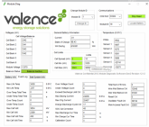
this is from today:
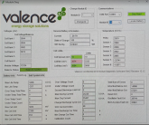
my question is why is the WH discharged not increasing (after about 4 charge/discharge cycles)
the charge cycle count is not changing.?
and why does the SOC not track down with the battery? ( if i run it down to 11v . . 126ah discharge, then connect to the laptop the SOC reads 98% lol)
in fact none of the data metrics are changing over time/use.?
i have 6x of these batteries and the same seems to be across the board . . .
so is it because the laptop is not connected and running the software all the time? . . .
does that imply that the REAL WH discharge could be much much more if these batteries have been in use without any laptop/software running?
********************
heres another example id-4
old pic when i got battery
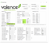
new pic today:
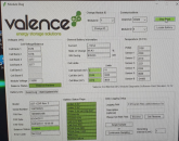
any idea why these pics dont add up?
this is when i first got the battery?
id19

this is from today:

my question is why is the WH discharged not increasing (after about 4 charge/discharge cycles)
the charge cycle count is not changing.?
and why does the SOC not track down with the battery? ( if i run it down to 11v . . 126ah discharge, then connect to the laptop the SOC reads 98% lol)
in fact none of the data metrics are changing over time/use.?
i have 6x of these batteries and the same seems to be across the board . . .
so is it because the laptop is not connected and running the software all the time? . . .
does that imply that the REAL WH discharge could be much much more if these batteries have been in use without any laptop/software running?
********************
heres another example id-4
old pic when i got battery

new pic today:

HI Guys,
any idea why these pics dont add up?
this is when i first got the battery?
id19
View attachment 23502
this is from today:
View attachment 23501
my question is why is the WH discharged not increasing (after about 4 charge/discharge cycles)
the charge cycle count is not changing.?
and why does the SOC not track down with the battery? ( if i run it down to 11v . . 126ah discharge, then connect to the laptop the SOC reads 98% lol)
in fact none of the data metrics are changing over time/use.?
i have 6x of these batteries and the same seems to be across the board . . .
so is it because the laptop is not connected and running the software all the time? . . .
does that imply that the REAL WH discharge could be much much more if these batteries have been in use without any laptop/software running?
********************
heres another example id-4
old pic when i got battery
View attachment 23504
new pic today:
View attachment 23503
As you have assumed, you need an external BMS connected for the internal stats to update. In any proper commercial application, there would always be an external BMS used with these batteries; they are simply not designed to be used without one. If you got the batteries from a DIYer who wasn't using with a BMS, then the WH stats, etc. could definitely be wrong. But otherwise, they should be ok.
mattyg
New Member
- Joined
- Aug 24, 2020
- Messages
- 3
As you have assumed, you need an external BMS connected for the internal stats to update. In any proper commercial application, there would always be an external BMS used with these batteries; they are simply not designed to be used without one. If you got the batteries from a DIYer who wasn't using with a BMS, then the WH stats, etc. could definitely be wrong. But otherwise, they should be ok.
It's been explained to me that the WH discharge includes a total discharge through the overall system vs. just from the battery itself. Hence, the WH discharge implies a higher cycle count than actual. This is consistent with what I have seen where the four batteries I have show almost exactly equal WH discharge, with a higher degree of cycle count variance than that implies. The cycle count, on the other hand, is how many instances of 1.766 kWh have been provided by the battery.
mattyg
New Member
- Joined
- Aug 24, 2020
- Messages
- 3
Folks, does anyone have information re: how to get the CANBUS monitoring software for PC?
I find the monitoring software (via serial) to be widely available; less so the CANBUS application to talk to the Valence BMS.
Appreciate any pointers - here or in PM
I find the monitoring software (via serial) to be widely available; less so the CANBUS application to talk to the Valence BMS.
Appreciate any pointers - here or in PM
dellmassive
New Member
- Joined
- Sep 21, 2019
- Messages
- 6
ok cool,As you have assumed, you need an external BMS connected for the internal stats to update. In any proper commercial application, there would always be an external BMS used with these batteries; they are simply not designed to be used without one. If you got the batteries from a DIYer who wasn't using with a BMS, then the WH stats, etc. could definitely be wrong. But otherwise, they should be ok.
ive just noticed that when linking up 4x batterys . . . as already mentioned adding the 5v from USB does nothing. (sleep green blink every 20
and that when you connect the lead nothing changes . . . . but as soon as you start the software "start read" they come into life (green blink @ 5sec rate) - but thats to any ID, i started polling an ID that i didnt have in the chain, but they all woke up !!!
so you dont even need to comunicate with any battery to wake them up . . . .
after a connection is closed (or the software times out looking for an ID) it takes about 4mins to revert back to sleep mode . . .
so . . . . . there must be something on the RS485 bus sent from the software that wakes the internal BMS up.
Its just HEX codes right?
has anyone managed to Hack a small circuit that can be used to poll the RS485 bus intermittently to keep the internal BMS alive for data monitoring / total WH collection, SOC etc etc ?
shouldn't be too hard right? . . . small RS485 transceiver and a PIC to run some code? . . . run from the battery's own supply?
anyone up for the challenge?
edit:
just noticed that when using the USB lead that has the blue/white data LEDS . . .
looks like that when you start the "Read" the software poles all the available battery ID`s TX data . .
and it appears that the battery responds with a poll RX data white LED.
so with 2x battery's i get 2x white RX blips, with 4x battery's i get 4x white RX blips. . .
.
Last edited:
The wake-up message sent by the BMS / Valence software is not battery specific, only the data read requests.ok cool,
ive just noticed that when linking up 4x batterys . . . as already mentioned adding the 5v from USB does nothing. (sleep green blink every 20
and that when you connect the lead nothing changes . . . . but as soon as you start the software "start read" they come into life (green blink @ 5sec rate) - but thats to any ID, i started polling an ID that i didnt have in the chain, but they all woke up !!!
so you dont even need to comunicate with any battery to wake them up . . . .
after a connection is closed (or the software times out looking for an ID) it takes about 4mins to revert back to sleep mode . . .
so . . . . . there must be something on the RS485 bus sent from the software that wakes the internal BMS up.
Its just HEX codes right?
has anyone managed to Hack a small circuit that can be used to poll the RS485 bus intermittently to keep the internal BMS alive for data monitoring / total WH collection, SOC etc etc ?
shouldn't be too hard right? . . . small RS485 transceiver and a PIC to run some code? . . . run from the battery's own supply?
anyone up for the challenge?
edit:
just noticed that when using the USB lead that has the blue/white data LEDS . . .
looks like that when you start the "Read" the software poles all the available battery ID`s TX data . .
and it appears that the battery responds with a poll RX data white LED.
so with 2x battery's i get 2x white RX blips, with 4x battery's i get 4x white RX blips. . .
.
And yes, it's certainly possible to make a simple BMS with a few £ worth of components. I have done exactly this:
GitHub - seb303/Arduino-XP-BMS: A BMS for Valence XP batteries, designed to run on Arduino or similar hardware.
A BMS for Valence XP batteries, designed to run on Arduino or similar hardware. - seb303/Arduino-XP-BMS
dellmassive
New Member
- Joined
- Sep 21, 2019
- Messages
- 6
thats awesome @seb303 ill look into making one up.
are we 100% sure that the cell "top-balancing" does not take place when the charge cycle is near the top end . . 13.7v up? with no data coms??
is the internal BMS asleep? . . . yet it does keep the status LED flashing green,yellow,red. . . so some of it must be awake?
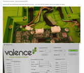
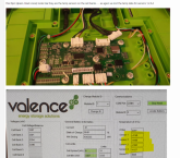
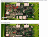
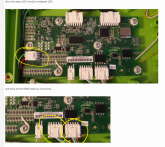
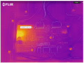
i got some thermals showing the top balance in action . . . but must admit i did have the data cable connected . .
think i need to redo this test and charge to top balance voltage and get the Flir on it. . . . i could also be seen on the Victron charger via the APP, with the current jumping all around from 0.1A to 3A while the top balance was taking place.
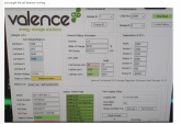
heres some of the pics from the test.
--

.

.

.
.
.

.
.
.
.
are we 100% sure that the cell "top-balancing" does not take place when the charge cycle is near the top end . . 13.7v up? with no data coms??
is the internal BMS asleep? . . . yet it does keep the status LED flashing green,yellow,red. . . so some of it must be awake?
i got some thermals showing the top balance in action . . . but must admit i did have the data cable connected . .
think i need to redo this test and charge to top balance voltage and get the Flir on it. . . . i could also be seen on the Victron charger via the APP, with the current jumping all around from 0.1A to 3A while the top balance was taking place.
heres some of the pics from the test.
--

.

.

.

.

.

.

.

.

.

Interesting tests, nice to get some confirmation of the internal hardware.are we 100% sure that the cell "top-balancing" does not take place when the charge cycle is near the top end . . 13.7v up? with no data coms??
is the internal BMS asleep? . . . yet it does keep the status LED flashing green,yellow,red. . . so some of it must be awake?
Regarding top-balancing: yes, 100% sure, the bleed resistors will not activate unless the internal BMS is awake (LED flashing every 5 seconds). Sure, it's never completely asleep as it's flashing the status LED and listening on the RS485, but it has been designed to use absolute minimum power for when the battery is in long term storage. The baud rate that it listens at when asleep is 9600 (as opposed to 115200 when awake). This suggests the processing speed of the internal processor has been clocked right down to save power.
If you charge the batteries at a high voltage without the internal BMS awake, then the cells may balance anyway, with the lower ones absorbing more power eventually, but you run the risk that the higher cells will go over voltage which will shorten their life.
dellmassive
New Member
- Joined
- Sep 21, 2019
- Messages
- 6
@seb303 i know you said it was 100% confirmed . . . . . but i just had to do my own tests.
i though you might like the data:
charger connected (already fully charged) up and ramped up to 14.6v for 15min . . . (well within the top-balence zone)

BMS sleeping, green blink every 20s . . . as expected . . . stone cold.
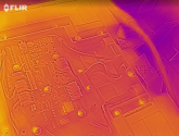
software and lead connected . .

we get an immediate response . .
BMS wakes up . . . green blink every 5sec.
and bleed resistors start heating up for banks 2,3,4.

then disconnect the lead . . . BMS goes to shelf mode again . . and resistors cool off. . .

reconnect again . . . . same happens. BMS wakes up . . . bleed resistors kick in..

so there we go, test complete. results as expected . .

i though you might like the data:
charger connected (already fully charged) up and ramped up to 14.6v for 15min . . . (well within the top-balence zone)

BMS sleeping, green blink every 20s . . . as expected . . . stone cold.

software and lead connected . .

we get an immediate response . .
BMS wakes up . . . green blink every 5sec.
and bleed resistors start heating up for banks 2,3,4.

then disconnect the lead . . . BMS goes to shelf mode again . . and resistors cool off. . .

reconnect again . . . . same happens. BMS wakes up . . . bleed resistors kick in..

so there we go, test complete. results as expected . .

dellmassive
New Member
- Joined
- Sep 21, 2019
- Messages
- 6
So the next question is . . . apart from @seb303 BMS keep alive tweek above . .
who's fitted a proper 150A/200A separate BMS to one of these . . ?
like a DALY for example?
easy enough to fit inline with the external negitive battery cable,
also easy to pick up the 4s tap wires for the cells.
could we expect:
Low volt disconnect?
high volt disconnect?
high current disconnect?
low temp disconnect?
common pin for charging after a disconnect?
Hi!
I may have in a near future 2 setup of 7 batteries together with a Valence BMS LV for each of them. This setup are used in electrical cars. I know they are sitting in a hangar for almost 3 years without a single charge, and I'm afraid batteries will be overdischarged...
Anyway, for the time being I'm preparing all the tooling I may need to check batteries condition, so I have already the RS485 adapter, AMP connectors and Valence XP12.12 software.
What would be needed to connect to the BMS and check them? I'm unable to locate the BMS software and I'm questionning if I can connect through the battery connector or if I need a CAN-USB adapter.
Also, in case of bad surprise, do you know of any source for these batteries in Europe?
So the next question is . . . apart from @seb303 BMS keep alive tweek above . .
who's fitted a proper 150A/200A separate BMS to one of these . . ?
like a DALY for example?
easy enough to fit inline with the external negitive battery cable,
also easy to pick up the 4s tap wires for the cells.
could we expect:
Low volt disconnect?
high volt disconnect?
high current disconnect?
low temp disconnect?
common pin for charging after a disconnect?
To be fair, my device isn't just a keep alive tweak for the internal BMS. It's a functioning external BMS which can monitor multiple batteries and signal an external load disconnect relay and charger.
Personally I prefer the idea of using theses batteries with the intended internal balance hardware, rather than having loads of extra external wires to tap between the cells.
Admittedly my BMS doesn't implement inter-battery balancing for serial set-ups, but this would just be a software update if someone could sniff the RS485 traffic from the Valence U-BMS and figure out the message to do this.
Similar threads
- Replies
- 2
- Views
- 250
- Replies
- 1
- Views
- 243


