diy solar

diy solar

Valence XP Super Thread

I left my 2 batteries connected in parallel with the BMS active for a few days before hooking up a charger. The biggest gap in cells between the two is 5mv. Most cells in the bank are 1-2mv apart. Is that what I should expect? I have a 2A lithium charger on the bank now with the BMS still active.
Yeah that's what you should expect. The cell block voltage variations won't vary too much until you get up to top balancing voltages. If you can get each cell up to 3.45 without any cell going over 3.8 on the first try it means they were pretty much balanced already. If you find it takes days or weeks then they were out of balance.
 
I'm planning on replacing 2 golf cart batteries in my travel trailer with one of the U27-12XP batteries. I upgraded my solar charge controller to the Renogy Rover Li 20A. I'm planning on using a BlueSea Low Voltage Disconnect set to 11.9V and will disconnect the battery entirely when winterizing the trailer to avoid charging while under freezing temps.

In the U27-12XP spec sheet, it states max charge voltage should be 14.6 and the float voltage is 13.8 but what about the equalize and boost voltages? Should they be the same as the max charge voltage?

View attachment 23125
Equalizing starts at 13.44 and continues up through 14.6. but isn't really that effective until it gets above 13.8.
 
I got my XPs hooked up yesterday and monitored closely throughout the day. My U-BMS has not arrived yet but so far so good. I'm using an Outback Flexmax 80 charge controller and wired up my XPs in the following format:
View attachment 10216
Except, all of the 24v (-) are equal length cables going directly from (-) post to a common bus bar terminal, and all 24v (+) are equal length cables going directly to a (+) bus bar terminal.

A couple of question/comments I wanted to address:

1). Regarding the battery terminal posts- when I received the batteries a week or two ago I cleaned the terminal bolts with WD-40. Travis had previously mentioned the loc-tite on the threads and needed spacers. Once the threads were cleaned both positive and negative terminal bolts will seat all the way to the head. No spacers are needed.

2). I wired up my battery bank in the manner showed in the photograph above 24 hours before installing and allowed the batteries to sit connected for 24 hours with no load and no charging.

3). I found this in a YouTube video comment:
View attachment 10217

Regarding the way to connect the battery communication wires, can anyone verify if this comment is true or not? I have been under the impression that it didn't matter how the communication wires were connected? Can anyone offer a schematic of how to configure my cabling once my U-BMS arrives?

Aloha,
Hey Manny....I'm still making my way through this thread so I'm not sure if anyone else has responded to you re your battery wiring. You will achieve better battery performance and balancing by moving your feeder cables to opposite ends of your battery bank.....i.e. Positive from top right battery, Negative from lower left battery. Even better would be to use separate cables for each battery and run them to a common bus.....be sure to keep all cables the same size and length and use a little dielectric grease on the connections to ensure a good low-resistance connection. You may find this link useful: http://www.smartgauge.co.uk/batt_con.html
 
@Travis -- I've posted this in another thread, but I think it deserves a mention here, too.. since this seems like a good place to post as well....

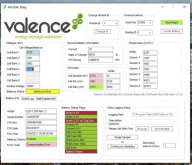
Here was my battery before I tried to recover it -- had three flags - "Under 2.3V", "Under 2.3V w/ Chg Current" and "Battery Failure"...

VP.jpg

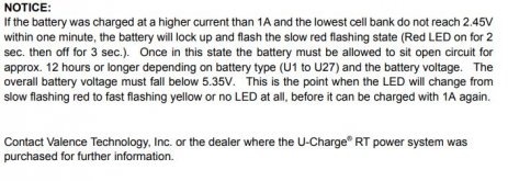
I popped the back cover and hooked Cell #2 up to a bench supply. I've managed to get the Cell 2 up to beyond 3.3V. This made the "Under 2.3V" flag disappear -- but the "Under 2.3V w/ Chg Curr" still remains. This seems a bit counter to the troubleshooting steps in the Valence User Manual for REV2:
V3.JPG

It seems I've done this -- I've got all cells above 3.3V... but in REV-1 it had a bit of a different story:

Capture.JPG
So it seems if this logic came through on the Rev-2 batteries -- in order to "reset" that flag, I'll need to bring the voltage down really low to basically turn off the LED again and then try again.

I'll test this theory -- but I want to balance this battery really well before I do it -- that way the cells all go really low together (at least roughly).

Will keep everyone posted what I discover.
 

Attachments

  • Capture2.JPG
    Capture2.JPG
    89.5 KB · Views: 20
Last edited:
@Travis -- I've posted this in another thread, but I think it deserves a mention here, too.. since this seems like a good place to post as well....

Here was my battery before I tried to recover it -- had three flags - "Under 2.3V", "Under 2.3V w/ Chg Current" and "Battery Failure"...

View attachment 24723

I popped the back cover and hooked Cell #2 up to a bench supply. I've managed to get the Cell 2 up to beyond 3.3V. This made the "Under 2.3V" flag disappear -- but the "Under 2.3V w/ Chg Curr" still remains. This seems a bit counter to the troubleshooting steps in the Valence User Manual for REV2:
View attachment 24724

It seems I've done this -- I've got all cells above 3.3V... but in REV-1 it had a bit of a different story:

View attachment 24721
So it seems if this logic came through on the Rev-2 batteries -- in order to "reset" that flag, I'll need to bring the voltage down really low to basically turn off the LED again and then try again.

I'll test this theory -- but I want to balance this battery really well before I do it -- that way the cells all go really low together (at least roughly).

Will keep everyone posted what I discover.
on the version 2 you can reset the board by disconnecting the power cable to it. It doesn't forget the flags but for some reason the light goes green after it boots back up. I don't remember which one supplies power to the board but you can probably figure that out pretty simply with a multimeter.
 
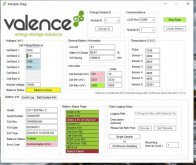
You're a real OG @Travis -- it's the MOLEX connector with the same terminals we use to charge an individual cell. Removing it and plugging it back in first made the light blink red/green (which freaked me out) but once it came back -- it wiped out the "Under 2.7V w/ chg curr" flag on my battery and now it is back to blinking Green! Woo! Gonna let the bench supply finishing bringing Cell #2 back to life!

Capture.JPG

Pull the power supply to the PCB makes sense since that basically is the same as allowing the battery to get so low that the PCB cannot operate. The Valence equivalent to "have you tried turning it off, waiting 20 seconds, and turning it on again?". I imagine if I drew the voltage down far enough that the PCB couldn't operate -- it would also clear that flag.

What is the "Battery Failure" flag about? Is this a flag that triggers (and stays triggered) if any failure mode occurs? Seems weird that it can be triggered and still be blinking green...

As a point of reference - this "recovery event" added to the "Reset Cnt" -- which I assume is the number of times a battery has gone from Red to Green... and all failure mode has been "undone". I say "all failure modes on purpose" because when I killed off just the "Under 2.3V" flag the "Reset Cnt" counter did not advance -- it only did so after both failures were undone.
1602228911103.png

So what does the "Battery Failure" flag then mean? Does the "Battery Failure" flag occur if there are any resets on it? It seems reasonable that it would be flagged since it is possible for the battery to over-drain itself and then recover without any intervention -- and thus you might want this flag to be triggered.

The OCD-side of me wants that flag gone -- but it's probably best I just ignore it and stress test this battery to see if it can handle some usage.
 
Last edited:
You're a real OG @Travis -- it's the MOLEX connector with the same terminals we use to charge an individual cell. Removing it and plugging it back in first made the light blink red/green (which freaked me out) but once it came back -- it wiped out the "Under 2.7V w/ chg curr" flag on my battery and now it is back to blinking Green! Woo! Gonna let the bench supply finishing bringing Cell #2 back to life!

View attachment 24725

Pull the power supply to the PCB makes sense since that basically is the same as allowing the battery to get so low that the PCB cannot operate. The Valence equivalent to "have you tried turning it off, waiting 20 seconds, and turning it on again?". I imagine if I drew the voltage down far enough that the PCB couldn't operate -- it would also clear that flag.

What is the "Battery Failure" flag about? Is this a flag that triggers (and stays triggered) if any failure mode occurs? Seems weird that it can be triggered and still be blinking green...

As a point of reference - this "recovery event" added to the "Reset Cnt" -- which I assume is the number of times a battery has gone from Red to Green... and all failure mode has been "undone". I say "all failure modes on purpose" because when I killed off just the "Under 2.3V" flag the "Reset Cnt" counter did not advance -- it only did so after both failures were undone.
View attachment 24727

So what does the "Battery Failure" flag then mean? Does the "Battery Failure" flag occur if there are any resets on it? It seems reasonable that it would be flagged since it is possible for the battery to over-drain itself and then recover without any intervention -- and thus you might want this flag to be triggered.

The OCD-side of me wants that flag gone -- but it's probably best I just ignore it and stress test this battery to see if it can handle some usage.
I think the reset count literally means how many times the board has been power cycled. I've seen people run their battery down so low that no lights were flashing not red or green but it did not trigger a reset count when recharged. It's possible the board was still keeping memory though because it may have had a little bit of power but not enough to light the LED any longer. But seeing how high your reset count is I think you're onto something with your thinking that it resets whenever the battery gets to dead.

I don't know what the battery failure count means or what it takes to trigger one of those. I would theorize it means that the board sees a real failure somewhere. Like maybe a cell block that self discharges very quickly. I've never seen that flagged yeat until you.
 
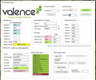
Well that ain't good -- also this isn't good... set my bench supply to 1A at 3.360V overnight last night to try and get this battery to balance and then this happened:
1602262349796.png

I have, yet another, failure flag for Under 2.3V. I think it is pretty conclusive evidence that Cell #2 is shot. Only when I crank up the amperage does that cell seem to increase in voltage. I'm no LiPo engineer -- but that doesn't look good.

It does appear that the "Reset Cnt" is related to how many times the PCBA has a "hard reset"... I unplugged it and plugged it back in again and that counter advanced -- so if you're looking at a battery that shows no signs of tampering with the rear cover (i.e. the sticker is in tact) this measures the number of times the voltage got so low that PCBA couldn't operate.

So just to be clear @Travis -- even on other batteries you've recovered there was no "Battery Failure" flag? Probably some very smart logic inside these batteries and I'd assume this is picking up on a pattern that isn't recoverable.
 
Last edited:
Well that ain't good -- also this isn't good... set my bench supply to 1A at 3.360V overnight last night to try and get this battery to balance and then this happened:
View attachment 24742

I have, yet another, failure flag for Under 2.3V. I think it is pretty conclusive evidence that Cell #2 is shot. Only when I crank up the amperage does that cell seem to increase in voltage. I'm no LiPo engineer -- but that doesn't look good.

It does appear that the "Reset Cnt" is related to how many times the PCBA has a "hard reset"... I unplugged it and plugged it back in again and that counter advanced -- so if you're looking at a battery that shows no signs of tampering with the rear cover (i.e. the sticker is in tact) this measures the number of times the voltage got so low that PCBA couldn't operate.

So just to be clear @Travis -- even on other batteries you've recovered there was no "Battery Failure" flag? Probably some very smart logic inside these batteries and I'd assume this is picking up on a pattern that isn't recoverable.
Correct I've seen no battery failure flags yet
 
(Had this posted in the beginners section, but it was mentioned that I should repost it here)

Hi all, I've been really appreciating reading this forum and have gotten lots of useful information from it so far. I have a few questions that I couldn't find the answers to on the Valence super thread post (maybe I just missed it?)

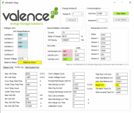
I've bought 2 of the U27-12xp batteries thinking they were like the smaller ones Will broke down on youtube with the internal BMS. (yes I know, should have done my homework better.) I'm planning to use them for an off-grid van build. I want to run the 2 Batteries in parallel and have them charge off of solar, the vehicles alternator via a DC-DC charger, and shore power when needed. My question is this: Do I need to worry about actively balancing the batteries, or will being in parallel do that for me? If not, will the Thunderstruck VC1 BMS activate the internal module to module cell balancing? ( I apologize if I am not using correct terminology, I'm very much a beginner). I know that the Thunderstruck needs to be hooked up to a contactor or relay to be able to disconnect the battery, but will it provide the 5v necessary to "wake up" the batteries internal balancing function? And finally, does anyone know if the Thunderstruck will trigger a contactor on low/high temperature based on the internal temp sensors in the batteries?

Thanks so much for taking the time to read my post! I'm very new to all this, so I really appreciate this wealth of information here! :)
I have a Thunderstruck VC1 BMS and it does activate the internal Cell balancing. You will notice the blinking light go from 20 seconds to 5 seconds. I have also hooked up the USB connection and can read the cells voltages. I have also used the USB connections I built and connect to the Valance software and checked out the Cell voltages and temps. Read this entire thread and you will have all the answers you need. Thanks to Travis for all the work and posting answers. I have two of the U27 - 12xp batteries in my 5th wheel. Works great!
 
Received this email from ThunderStruck today:

Dear VC1 Users,

The VC1 has some new features we would like interested users to know about. We will list the changes here and are including the latest manual for reference.

1) Temperature limits for each cell in the module can now be set in the VC1 interface. Temperatures exceeding the limits (high and low) will result in opening the HLS and LLS circuits until the condition normalizes.

2) The VC1 automatically initiates module level cell balancing, but not inter-module balancing (between modules). This feature was present in earlier version releases, but was verified recently through thermal and cell voltage tracking.

If you have questions about these or any other features of the VC1, please let us know.

Thank you for supporting our work at ThunderStruck Motors.

John
 
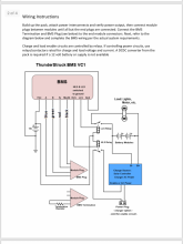
who has the Thunderstruck BMS VC1 hooked up to their valence batteries. could you please share with me and show photos of your set up. I am trying to figure this out. Am I hooking up any wires to the HLS, LLS and NC ports of the Thunderstuck BMS?
 
who has the Thunderstruck BMS VC1 hooked up to their valence batteries. could you please share with me and show photos of your set up. I am trying to figure this out. Am I hooking up any wires to the HLS, LLS and NC ports of the Thunderstuck BMS?
Tried to upload manual but didn’t work out.

Have you read it?

Everything you need to know is in it. It can be downloaded from ThunderStruck’s site.

Here is the schematic.

The feature of the VC1 triggering relays based on a high and low value is optional. If you want the protection on your power input and output side, then you’ll want to try to set your system up to make use of them. Some devices (like a solar charge controller) might work directly while others might require a separate relay for hard disconnect.
 

Attachments

  • 05BDC1E7-D1A6-40F5-A697-357E2D657685.png
    05BDC1E7-D1A6-40F5-A697-357E2D657685.png
    220.9 KB · Views: 35
  • 00586DAB-1CF0-4044-9A2E-124D73D8FCB5.png
    00586DAB-1CF0-4044-9A2E-124D73D8FCB5.png
    391.3 KB · Views: 31
Last edited:
I have a 36 volt trolling motor I am using these u27-12xp batteries. I do have the same diagram you do but I do not know how to read electrical diagrams.
 
I have a Thunderstruck VC1 BMS and it does activate the internal Cell balancing. You will notice the blinking light go from 20 seconds to 5 seconds. I have also hooked up the USB connection and can read the cells voltages. I have also used the USB connections I built and connect to the Valance software and checked out the Cell voltages and temps. Read this entire thread and you will have all the answers you need. Thanks to Travis for all the work and posting answers. I have two of the U27 - 12xp batteries in my 5th wheel. Works great!
Awesome! I am going to pick one up for sure. I'm very grateful of all the information here, it's been super useful!
 
Received this email from ThunderStruck today:

Dear VC1 Users,

The VC1 has some new features we would like interested users to know about. We will list the changes here and are including the latest manual for reference.

1) Temperature limits for each cell in the module can now be set in the VC1 interface. Temperatures exceeding the limits (high and low) will result in opening the HLS and LLS circuits until the condition normalizes.

2) The VC1 automatically initiates module level cell balancing, but not inter-module balancing (between modules). This feature was present in earlier version releases, but was verified recently through thermal and cell voltage tracking.

If you have questions about these or any other features of the VC1, please let us know.

Thank you for supporting our work at ThunderStruck Motors.

John
Thanks for sharing that email, that's good to know that you can set a high/low temp cut off with it. If it only balances the cells in the individual modules, do I need to worry about the modules being out of balance with each other with two of them in parallel? (assuming I've done a good job balancing them before connecting them together)
 
Thanks for sharing that email, that's good to know that you can set a high/low temp cut off with it. If it only balances the cells in the individual modules, do I need to worry about the modules being out of balance with each other with two of them in parallel? (assuming I've done a good job balancing them before connecting them together)
No prob.

I don’t believe a balancer/equalizer is required if you are running in parallel. With batteries in series, you need to be concerned that each battery is balanced with another just as you do with the individual cells and modules that make up the individual battery.

However in parallel, a weak battery could certainly bring down your capacity so it would be wise to monitor each battery using the VC1 software. As long as each battery is going through it’s balancing process and reaching full capacity, you should be fine.

I did reach back out to ThunderStruck to confirm if inter-balancing was still a feature they were working on for the VC1 as I had originally been told in was in the works. If they get that working, the VC1 will be able to do what most people want -intra and inter balancing, temperature monitoring, and triggering of disconnects.

I’ll report back if I hear from them.

BTW, if anyone is using a Victron smart charge controller and has added a VC1 or plans to add one, you should be able to have the VC1’s HLS output trigger the MPPT directly to disable charging in the event of over voltage by using the VE.direct ports RX pin by setting its function within the software to remote on/off which would eliminate the need for a hard disconnect device. I have not tested this, but it looks to be possible based on the specs.
 
Last edited:
New to the Site but have been lurking for a while.
Im setting up a solar /battery system for my new Promaster van.
I have a 305w Solar panel
2 of the XP U27-12XP batteries
Kisae DMT 1250 DC to DC charger Controller - http://www.kisaepower.com/products/battery-chargers/model-dmt-1250/
* Allows me to charge from alternator as well.
Kisae ABSO 200Watt Inverter/ Charger

I like many of you was quick to buy these batteries at a good deal, and never knew the trouble of cell balancing, over charging and over heating. I figured that the Charge controller could take car of that.
Questions to the pros out there.

If I decide to run only one of the Valence Batteries? Do I need to worry about cell balancing and stimulating the Battery's BMS? My Kisae Charge controller has multiple user settings to set limits on charging and discharge.
Secondly If I decide to run both batteries in Parallel, keeping the system at 12V. What do I really need to worry about with these batteries?
Both have less than 400 charge cycles and are balanced at 13.3 V right now.

All of this Computer hook up and external BMS back and forth is confusing me more than I thought it would.

Bottom line.
If I just hook these up in Parallel with the equipment I have, without balancing the cells every month ( pain in the ass IMO), am I just going to limit some of my output, shorten the battery life, etc. Or would there be something more serious that could happen?
Same questions if I just run a single battery instead?

If I do need a Valence BMS, Can i just hook it up and forget about it and let it do its job or is it something I have to constantly monitor.
I am beginning to think it is more trouble than its worth to use these batteries

Thanks in advance.
 
Last edited:
Back
Top