Interesting, and very helpful. Are the black batteries newer or older than the green ones?I think they're slightly different capacity so it will be harder to stay away from a severely undervoltage cell in a series setup if you mix the black and green. Parallel will be fine.
If you paid for green ones and you got black ones I'd be getting your money back if I were you. Especially if you bought a lot of them. The XP battery line is especially simple and awesome to set up in large battery Banks because of the simplicity with having one single BMS cover the entire battery Bank in any configuration.
I don't know if the black ones work with the thunderstruck BMS but hopefully they do because then you'll have a cheap way to use them safely. I know they don't work with the external BMS I sell that works with the green batteries.
Does anyone know if the battery history and cell voltages can be read with the RS 485 cable and a laptop computer? What I'm getting at is is there any way to wake up and keep awake the internal cell balancing computer? Maybe they could be kept awake by connecting to the old style BMS that matches the black batteries. And they'll be awake and maintaining cell balance even though the series parallel count is completely wrong in the configuration inside the BMS.
The black batteries really haven't been thoroughly figured out by the aftermarket community. Maybe best to delete its internal computer and replace it with an aftermarket BMS designed for however many cells you're using in your system.


You are using an out of date browser. It may not display this or other websites correctly.
You should upgrade or use an alternative browser.
You should upgrade or use an alternative browser.
Valence XP Super Thread
- Thread starter Travis
- Start date
OlderInteresting, and very helpful. Are the black batteries newer or older than the green ones?
Excellent reading! I have and installing an 8kw Growatt inverter, (8) 395watt panels and (4) u27-12XP's. The discussions has helped me to finally get the USB and wiring complete and start talking to my u27-12XP's on COM3. I get so far as it locates the battery and knows it's make, and it's Revision and ID etc.. But it then gives me an "Access to the path" error, even though I have set the logging path. I have tried the path to my valence file with a log folder, then to my desk top with a log folder etc., tried on two different machines, I am set as an Administrator, and even deleted the software and used your link above. But it still gives me the "Access to the path" error as shown in the screen shot below.#13 Balancer On The Cheap.
Maybe you don't need a BMS at all? Like if your inverter shuts down before the battery gets too low and your charge controller is reliable and you have a cheap aftermarket battery to battery balancer. & Every once in awhile in order to activate the internal cell balancers you could hook up the batteries to your laptop to enable the cell balancing during an equalization charge. During normal cycling you would simply stay away from the upper percentages like try only charging it to 13.85 volts. Give or take a little bit with some experimentation you can probably come up with the right upper voltage limit that doesn't put any cell in danger. The manual says keep them under 4 volts but starts getting giving warnings when it's over 3.8 volts.
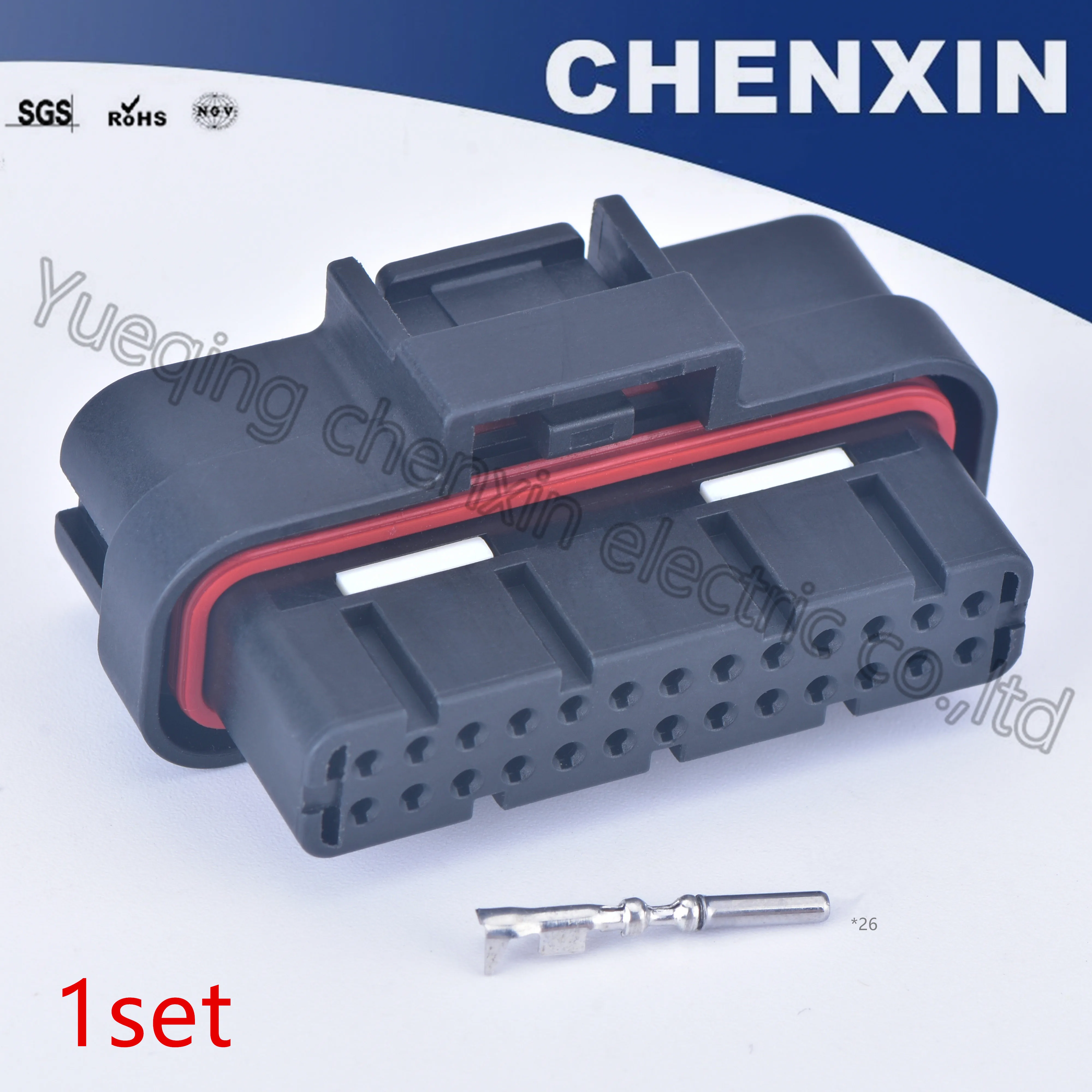
Here is a 2-channel balancer. This will work for 1 string of batteries in series for a 24 volt battery Bank. You will need one balancer for each string. Although I'm not impressed with its amperage abilities. It claims 10 amps but when I measured I was only able to get 0.2 amps moving from the highest battery to the lowest battery. I'm worried it won't pass enough amperage and if you choose this option you will have to keep an eye on it in the upper and lower voltage range to prove to yourself that it's working properly. Then you can relax or maybe you'll decide it's not good enough.
Here's a 4-channel balancer. this will work for two strings of batteries (4 batteries) in a 24v battery Bank. And it will also work for one string at 48 volts which is also 4 batteries. If I were doing a series-parallel setup I would keep all series strings independent of each other except at there main terminating ends of the string. Each series string would have its own cheap balancer. So You'll have to buy more balancers if you have more than 4 batteries. It's the same cheap style as the two channel above that didn't move many amps for me so take the precautions mentioned previously.
Amazon.com: Battery Equalizer 48V - Battery Voltage Balancer, Max 4 × 12V Battery Bank Extend Battery Life 1 Year and More support Gel Flood AGM Lead Acid Lithium Battery HA02 Balancer(Battery Equalizer 48V): Automotive
Buy Battery Equalizer 48V - Battery Voltage Balancer, Max 4 × 12V Battery Bank Extend Battery Life 1 Year and More support Gel Flood AGM Lead Acid Lithium Battery HA02 Balancer(Battery Equalizer 48V): Energy Controllers - Amazon.com ✓ FREE DELIVERY possible on eligible purchaseswww.amazon.com
Do-IT-YOUR SELF BMS balancer for programmers.
Here's an interesting read where a guy starts programing his own balancer for valence batteries. He has had success enough to be useful and is active in this and is looking for programmers to help with the project. https://diysolarforum.com/threads/interfacing-with-valence-built-in-monitoring.2183/
RELAY:
Here's a link to a quality used high amperage relay. Ev200a for only $30. Most eBay sellers are asking $100. This is a $200 relay. https://ebay.us/K8VX8J
STATE OF CHARGE / VOLTAGE PROTECTION:
Here is a cheap Chinese battery capacity meter that appears to have the ability to primitively protect the batteries from high and low voltage if you purchase a high current relay to go with it. I say primitively because this will only base it's disconnect protection from total series voltage not individual cell voltage so if one starts to wander it won't have a clue. I bought one of these and I'm had screen errors. The screen gets all garbally. Amazon sent me replacement February 2020 and it's working. I tested its relay control and it shorted closed (broke) when I tried to have it control a large relay so you may have to replace the transistor with a larger one or else power a small relay and then use the small relay to power the large relay. This will also show you percentage of state of charge if you programmed the correct amp hour capacity into the meter. And remember you can always plug the Valence into the laptop in order to view the on board computer that will tell you state of charge and lots of other useful info. Heads up though the valence state of charge meter probably needs to be calibrated by doing a few complete charge, discharge, charge and top balance cycles.
I've noticed the valence batteries internal on board state of charge meter is actually intelligent and adjusts its capacity on the fly according to how much wattage you're pulling out of the battery. When I pull wattage out faster I've seen as much as a 30% reduction in the projected capacity. But when I pull power out very slowly I can get dang near 100% of its original rated capacity out during a externally metered capacity discharge test.
#14 rs-485 ON BOARD COMPUTER communicating with laptop.
Plugging a laptop into the communication plug of the valance will show you % of charge remaining on an individual battery, temperature, voltage total and voltage of each cell, among many other things. But it only shows one battery at a time which is kind of annoying. I'm not sure which temperature sensor is where inside the battery. I get some very wild temperature readings uncensor 5 & 6 that very a lot between batteries of the same temperature.
VALENCE software:
Here is a link to download a zip file containing the valence software to connect the laptop to its onboard computer. This one has three tabs in the bottom section and I heard there is a version that has four tabs if you know where I can get it let me know. It's for Windows only and will not work with Apple unless you run Windows in a virtual machine on your Apple with all kinds of hassle. If you're not plugging the batteries into a laptop I would suggest plugging the two communication cables into each other on the same battery to form a sort of handle that you should not lift the battery with. This will keep the metal pins inside the connectors clean and corrosion free. When you open the software after you install it you'll need to find the ModuleDiagG2.exe file in the program's folder (x86) folder. Right click on it and run as administrator. On my computer I was not able to right click on the desktop shortcut to accomplish this. Now you should have the valence program running and you'll see the main valence page with mostly blank boxes.
Next you need to set the logging path in the battery info tab. Near the bottom right side click on browse and choose a place somewhere on your computer probably in my documents folder you can create a folder called valence log files or something and choose that folder. Every once in a while like if my laptop goes to sleep and then wakes back up again I noticed the data reported in the software no longer reflects the correct battery when I switch between batteries. If this happens I simply restart the program and it's good to go again. If anyone knows how to write some basic code so that we can see the info on all the batteries on a live active spreadsheet that would be great if you help me out with that I'll share it with everyone. https://drive.google.com/file/d/1qCrYA6lAHl2Cx31xhAd_p3dqowhRImJ8/view?usp=drivesdk
RS485 USB ADAPTER:
There are several to choose from. Some of them don't Supply Power to the valence onboard computer like it needs. The one I'm using doesn't so I literally had to get a 4 volt battery and run 4.2v into the communication plug on the valence battery. After you get the adapter in the mail you'll have to plug it into the USB port on your computer. I used Windows 10 and it automatically installed the drivers. If you're using an older windows version or something you might have to install the drivers yourself. Maybe the adapter comes with a disc or something I'm not sure. Here's a link to one that does Supply power like we need https://amzn.to/2zn3S6s
PIN OUT COMMMUNICATIONS connector diagram:
In this picture that you can also find in the user manual you will see a connector that you can purchase from a link a few paragraphs below. You would want to crimp wires to this connector and run them over to the rs-232 to rs-485 USB adapter. It will label each pin in the connector.
This is just a screenshot of Page 47 of the user manual. https://drive.google.com/file/d/14LlaJXSz5dLehfCwMOcftLAKhKveqAl8/view?usp=drivesdk
COM PORT:
Now about choosing the comport. In the valence software click the comport drop down and you'll see that it's blank. There are no comm ports to choose even if have you previously set up the comport properly. You'll have to go to your hardware page to discover the com number. Then go to the software and literally type com7 or com5 or whatever the number was. And remember no spaces. Next look at the ID number I wrote on the battery and choose that in the drop-down. Connect to the communication wire from the balance computer into the rs485 USB adapter Then click start communication. You should now be seeing all the boxes filled with data from the batteries onboard computer. You can switch between batteries without ending and restarting communication but it only shows one battery at a time which is kind of annoying.

escheie
New Member
- Joined
- Jan 31, 2022
- Messages
- 3
I am having a similar problem in that I wanted to upgrade from 12 volts to 24 by adding another U27 XP to my existing setup of three (the green ones). I bought what was advertised as a green 138AH battery, and what I got was a black one with the label stating it has 130AH capacity. So now I am hesitant to hook all four up in series/parallel to get 24 volts. Does anyone know whether the older black batteries really are of a different capacity, or did they test and decide to up-rate the same battery for marketing purposes. (If the latter is the case, I'd probably be OK.) Any help greatly appreciated.I think they're slightly different capacity so it will be harder to stay away from a severely undervoltage cell in a series setup if you mix the black and green. Parallel will be fine.
If you paid for green ones and you got black ones I'd be getting your money back if I were you. Especially if you bought a lot of them. The XP battery line is especially simple and awesome to set up in large battery Banks because of the simplicity with having one single BMS cover the entire battery Bank in any configuration.
I don't know if the black ones work with the thunderstruck BMS but hopefully they do because then you'll have a cheap way to use them safely. I know they don't work with the external BMS I sell that works with the green batteries.
Does anyone know if the battery history and cell voltages can be read with the RS 485 cable and a laptop computer? What I'm getting at is is there any way to wake up and keep awake the internal cell balancing computer? Maybe they could be kept awake by connecting to the old style BMS that matches the black batteries. And they'll be awake and maintaining cell balance even though the series parallel count is completely wrong in the configuration inside the BMS.
The black batteries really haven't been thoroughly figured out by the aftermarket community. Maybe best to delete its internal computer and replace it with an aftermarket BMS designed for however many cells you're using in your system.
I have a U-BMS-LV in hand. Where can I get the CAN bus to USB adapter? (Not the RS485 adapter for talking to the individual modules, I already have that working). And also the CAN software?
this work?
amazon.com
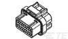
on the bms there are two 26 pin connectors, what are these called so I can buy a plug end to make my wiring harness? The 26 pin IDC connectors with the flat cables look like they might fit but I dont have any handy or a test fit.
this work?
amazon.com
on the bms there are two 26 pin connectors, what are these called so I can buy a plug end to make my wiring harness? The 26 pin IDC connectors with the flat cables look like they might fit but I dont have any handy or a test fit.
Pretty sure they are Tyco Superseal 1.0I have a U-BMS-LV in hand. Where can I get the CAN bus to USB adapter? (Not the RS485 adapter for talking to the individual modules, I already have that working). And also the CAN software?
this work?
amazon.com
on the bms there are two 26 pin connectors, what are these called so I can buy a plug end to make my wiring harness? The 26 pin IDC connectors with the flat cables look like they might fit but I dont have any handy or a test fit.
I used to have the part number but can’t find it now.
I may have an extra set of connectors — PM me and I’ll check for you.
I think this is what you’re after:
 www.te.com
1473712-2 : Automotive Housings
Get 1473712-2 Automotive Housings specs, pricing, inventory availability, and more from TE Connectivity. Get a sample or request a quote.
www.te.com
I have a U-BMS-LV in hand. Where can I get the CAN bus to USB adapter? (Not the RS485 adapter for talking to the individual modules, I already have that working).

I have ordered the following con nectors. They are working perfectly:I have a U-BMS-LV in hand. Where can I get the CAN bus to USB adapter? (Not the RS485 adapter for talking to the individual modules, I already have that working). And also the CAN software?
this work?
amazon.com
on the bms there are two 26 pin connectors, what are these called so I can buy a plug end to make my wiring harness? The 26 pin IDC connectors with the flat cables look like they might fit but I dont have any handy or a test fit.
6.5US $ |26p 1.0mm Super Seal 26 Pos Pin Modified Ecu Connector Female Auto Computer Connector 1473712-1 1473712-2 - Cables, Adapters & Sockets - AliExpress
Smarter Shopping, Better Living! Aliexpress.com
Any chance you have an extra you would be willing to sell me? If not I'll order those from China and just wait a while for deliveryI have ordered the following con nectors. They are working perfectly:
6.5US $ |26p 1.0mm Super Seal 26 Pos Pin Modified Ecu Connector Female Auto Computer Connector 1473712-1 1473712-2 - Cables, Adapters & Sockets - AliExpress
Smarter Shopping, Better Living! Aliexpress.comwww.aliexpress.com
")
ValkyrieVanLife
New Member
- Joined
- Apr 9, 2020
- Messages
- 19
Newbie here, would love some help TIA! I’ve got a blinking red light. It shows a status flag of “Under 2.3V w/ Chg Curr”. I’ve tried the user manual thing of charging at 1 Amp, but it’s up to 98.82 state or charge and still blinking red light. It also says balancing status is inactive. If anyone knows what to do and can help explain in super basic terms, I would be super grateful! 
I've had the same problem before. I was able to clear the red light and error by opening the access to the balance board, and disconnect the balance cable for a minute, then reconnect it. As long as the error is not still occurring, it should clear out.Newbie here, would love some help TIA! I’ve got a blinking red light. It shows a status flag of “Under 2.3V w/ Chg Curr”. I’ve tried the user manual thing of charging at 1 Amp, but it’s up to 98.82 state or charge and still blinking red light. It also says balancing status is inactive. If anyone knows what to do and can help explain in super basic terms, I would be super grateful! View attachment 103539
Keep on charging the battery, once you get closer to 13.4-13.7 the balancers will kick on and start bleeding off the highest cells. If any one cell gets up to 3650 then stop the charging until it goes back down. Keep on going until you can get it all the way up to 14.2v without any balancing going on. It might take a few hours, or might take a couple of weeks, depending on how unbalanced they are.
Be sure to keep the software on and running - it will not enable the balance resisters if the software is not running
Be sure to keep the software on and running - it will not enable the balance resisters if the software is not running
ValkyrieVanLife
New Member
- Joined
- Apr 9, 2020
- Messages
- 19
This is a little above my knowledge level - where in the software do I see the current voltage? Is it the “Module voltage” box - at 13.293?Keep on charging the battery, once you get closer to 13.4-13.7 the balancers will kick on and start bleeding off the highest cells. If any one cell gets up to 3650 then stop the charging until it goes back down. Keep on going until you can get it all the way up to 14.2v without any balancing going on. It might take a few hours, or might take a couple of weeks, depending on how unbalanced they are.
Be sure to keep the software on and running - it will not enable the balance resisters if the software is not running
ValkyrieVanLife
New Member
- Joined
- Apr 9, 2020
- Messages
- 19
Do you know if there are any videos or diagrams that show how to do this? I’m so new to this, I’m not sure how.I've had the same problem before. I was able to clear the red light and error by opening the access to the balance board, and disconnect the balance cable for a minute, then reconnect it. As long as the error is not still occurring, it should clear out.
Yes, module voltage is the battery itself. Cell Bank 1,2,3,4 are the 4 individual blocks inside that are wired in series. From your photo, 3.323v+3.323+3.324+3.323=13.293vThis is a little above my knowledge level - where in the software do I see the current voltage? Is it the “Module voltage” box - at 13.293?
You remove the tiny screws on the side of the battery to take off the plastic side cover, inside there is a circuit board.Do you know if there are any videos or diagrams that show how to do this? I’m so new to this, I’m not sure how.
escheie
New Member
- Joined
- Jan 31, 2022
- Messages
- 3
I had a similar situation, and I got the red light to clear by using a power supply set to 13.6 volts. I watched it carefully, and when one of the cells started to get too high, I lowered it to 13.4 and kept it there until everything was top balanced. The red light went out and the battery has been working since then (although it suffered some damage and doesn't reach the same voltages as the rest of the bank).
I can no longer suggest active balancers that don't have a cut in voltage set point for lfp batteries. Valence is lfp. What recently happened to me is when one cell has a slow self-discharge the balancer in the picture caused all the others to dump their power into its bank of 4 which raises the three others and causes them to go over voltage next time you do a top balance which in my case is nearly every day as the sun comes out. The original valance ubms caught the over voltage condition and shut the pack down for protection. I've gone through hundreds of these batteries and I rarely have issues but some sets simply need stronger balancers because of their condition. If your batteries are having trouble staying balanced after an initial top balancing I recommend adding a JK active BMS or even using the JK BMS to completely delete the original valence boards. If you have a lot of batteries an original valence ubms is beneficial.
Keywords: u27-12xp U27-24XP
Keywords: u27-12xp U27-24XP
Attachments
Similar threads
- Replies
- 2
- Views
- 252
- Replies
- 1
- Views
- 245