


You are using an out of date browser. It may not display this or other websites correctly.
You should upgrade or use an alternative browser.
You should upgrade or use an alternative browser.
Van Conversion Wiring Diagram, Please Review
- Thread starter dudedogvan
- Start date
dudedogvan
New Member
- Joined
- Mar 10, 2022
- Messages
- 90
So you're saying I should use lever nuts instead of splicing wires?I think so.
I like Wago 221-41x and 221-61x for non-waterproof joinery of 10 awg and smaller.
Remember to provide for strain relief.
I plan on having a carbon monoxide detector.Carbon monoxide is a good idea too as you will be using propane.
John Frum
Tell me your problems
- Joined
- Nov 30, 2019
- Messages
- 15,233
I'm not sure how you splice but, I like lever nuts for fast easy joinery for 10 awg or less and 24 service amps or less.So you're saying I should use lever nuts instead of splicing wires?
No smoke detector?I plan on having a carbon monoxide detector.
How do you splice?
dudedogvan
New Member
- Joined
- Mar 10, 2022
- Messages
- 90
So actually the deal with carbon monoxide, smoke, and propane instead the van is this: CO will only be be present in small amounts when I'm burning the propane. Proper ventilation will be provided by the Maxxair fan and an open window. When I'm not cooking with the propane, the concern would then be a propane leak inside the van. Ethyl Mercaptan, according to the internet, is the additive in propane that allows one to smell it in the case of a leak. CO detectors do not detect propane leaks. I am the propane leak detector. Smoke is the same, if there is smoke I will know because I'm the smoke detector. Lastly, propane tanks are over-engineered and they have pressure release valves. I will close the main valve on the tank after every use. I spoke too soon on the CO detector. I plan to probably have nothing. I see little risk really.No smoke detector?
How do you splice?
I was planning to butt splice with heat shrink. I had never seen a lever nut until you educated me. I don't think I'll be using lever nuts, probably butt splicing. I think I have soldered once maybe, haha, but I may do some soldered connections with heat shrink.If moisture is a concern then you should do waterpoof joinery.
dudedogvan
New Member
- Joined
- Mar 10, 2022
- Messages
- 90
After this discussion, I think I'll use 12awg with 15A fuses for the low current circuits.Say 10 amp fuses for for 14 awg or 15 amp fuses for 12 awg?
John Frum
Tell me your problems
- Joined
- Nov 30, 2019
- Messages
- 15,233
I'm not a fan of butt splices.I was planning to butt splice with heat shrink. I had never seen a lever nut until you educated me. I don't think I'll be using lever nuts, probably butt splicing. I think I have soldered once maybe, haha, but I may do some soldered connections with heat shrink.
I'm hoping to never use my soldering iron ever again.
dudedogvan
New Member
- Joined
- Mar 10, 2022
- Messages
- 90
Why for both statements?I'm not a fan of butt splices.
I'm hoping to never use my soldering iron ever again.
So you like lever nuts?
John Frum
Tell me your problems
- Joined
- Nov 30, 2019
- Messages
- 15,233
Butt splices need strain relief and then you end up with an ungainly loop.Why for both statements?
I see a lot of people that do them inline without proper strain relief and tweaks my OCD.
Yes, for joints in dry environments.So you like lever nuts?
Its been so long since I looked into waterproof/water resistant joints.
I vaguely recall there are gel filled offerings kind of like a Scotchlok but for bigger wires.
Anybody have a good product for this?
dudedogvan
New Member
- Joined
- Mar 10, 2022
- Messages
- 90
@smoothJoey
Thanks, I was just making sure I had all the tools necessary. You're on top of it!
I really appreciate all your help on this project.
Thanks, I was just making sure I had all the tools necessary. You're on top of it!
I really appreciate all your help on this project.
SniperX
Solar Enthusiast
- Joined
- Apr 1, 2021
- Messages
- 330
and this is WHY I read and read... T H A N K S for the link to those twin wire ferrules. I had no idea they were a thing but wondered how people do 2 or 3 wires besides splicing in. I need to do 3*2AWG and I have no idea how to do that because the lugs will end up being too much for the terminal. I know a ferrule won't work but at least I know about these now!This is a less expensive build.
The trick is double up the 10 awg wires into the solar charge controller.

Insulated & Non-Insulated Twin Wire Ferrules | Ferrules Direct
Our insulated & non-insulated twin wire ferrules are for use in factory wiring only & power or control circuits.Contact us with any further information.www.ferrulesdirect.com
Code:legend { {} { functional block } nnn|NNN| { fused busbar position where nnn is wire size in awg and NNN is the fuse rating in amps } nnn|UUU| { un-fused busbar position where nnn is wire size in awg } <-> { bi-directional current flow } -> { uni-directional current flow } <- { uni-directional current flow } dpst { double pole single through switch } @ { back reference } } dc_domain { fuse_block { feeders { positive<->100A_breaker<->battery negative<->shunt<->battery } branches { positive { 010|030|<-scc.out 010|030|<-scc.out 010|030|->fan 010|030|->fridge 010|030|->combo socket 010|030|->combo socket 016|001|->shunt_positive } negative { 010|UUU|->scc.out 010|UUU|->scc.out 010|UUU|<-fan 010|UUU|<-fridge 010|UUU|<-combo_socket 010|UUU|<-combo_socket 010|UUU|<->chassis_bond } } scc { in { positive<-dpst<-panels(10 awg) negative->dpst->panels(10 awg) } out { positive@ negative@ } } } }
John Frum
Tell me your problems
- Joined
- Nov 30, 2019
- Messages
- 15,233
If you don't mind me asking, why do you need to join 3x 2 awg wires together?and this is WHY I read and read... T H A N K S for the link to those twin wire ferrules. I had no idea they were a thing but wondered how people do 2 or 3 wires besides splicing in. I need to do 3*2AWG and I have no idea how to do that because the lugs will end up being too much for the terminal. I know a ferrule won't work but at least I know about these now!
If I know why I can probably help you.
SniperX
Solar Enthusiast
- Joined
- Apr 1, 2021
- Messages
- 330
Following this convo and I am learning a lot. Question: "But because I used 6 awg wire we can use a 100 amp fuse which has lower resistance" Is this because 6 awg is rate for 115A so the 100A would work (rounding down)? I am trying to see if I understand the concept here. Thanks.The solar charge controller has 2 sides, pv input and system output.
A single string of panels does not require a fuse.
The system side amperage could be up to ~50 amps.
The smallest fuse we could use on the system side is 60 amps.
50 amps / .8 fuse headroom = 62.5 amps
So we round it down to 60 amps.
But because I used 6 awg wire we can use a 100 amp fuse which has lower resistance.
On the second drawing I used 2 * 10 awg each with a 30 amp fuse.
30 amps is the max ampacity for a branch circuit on a fuse block.
SniperX
Solar Enthusiast
- Joined
- Apr 1, 2021
- Messages
- 330
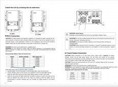
Not to take from the OP's questions, and I know you hate the Growatt's, lol, but I have the 12kw 250v 120A version and going from the battery busbars, then to T-Class fuse, then to disconnect, then to busbar and from the busbar, the manual says to use 3*2awg wire.If you don't mind me asking, why do you need to join 3x 2 awg wires together?
If I know why I can probably help you.
Attachments
John Frum
Tell me your problems
- Joined
- Nov 30, 2019
- Messages
- 15,233
Correct.Following this convo and I am learning a lot. Question: "But because I used 6 awg wire we can use a 100 amp fuse which has lower resistance" Is this because 6 awg is rate for 115A so the 100A would work (rounding down)? I am trying to see if I understand the concept here. Thanks.
SniperX
Solar Enthusiast
- Joined
- Apr 1, 2021
- Messages
- 330
You are a patient but great teacher. I always look forward to you chiming in.Correct.
John Frum
Tell me your problems
- Joined
- Nov 30, 2019
- Messages
- 15,233
I don't hate them.Not to take from the OP's questions, and I know you hate the Growatt's, lol, but I have the 12kw 250v 120A version and going from the battery busbars, then to T-Class fuse, then to disconnect, then to busbar and from the busbar, the manual says to use 3*2awg wire.
Not a fan, but I don't hate them.
12000 ac watts / .85 conversion factor / 48 volts low cutoff = 294.117647059 service amps.
294.117647059 service amps / .8 fuse headroom = 367.647058824 fault amps.
That means the minimum you could use is 4/0 awg with a 400 amp fuse.
If you use 2 awg you should land them on three different studs and use a 200 amp fuse on each wire.
2awg is ~= 35mm2.
3 * 35 = 105mm2 which is pretty close to 4/0 awg.
4/0 awg ~= 120mm2.
I don't know what glue they are sniffing but hardly anyone in the field is going to do 3x 2 awg.
Check with them to make sure they won't be dicks about the warranty though.
Similar threads
- Replies
- 4
- Views
- 373
- Replies
- 2
- Views
- 162
- Replies
- 23
- Views
- 821