Howdy,
I'm in the process of trying to figure out how to get all my wiring for my van build/conversion set up, so I thought I'd pop over here and ask for help. Just wanted someone to take a look at my wiring diagram, and give me some advice on what else I should do/not do.
206Ah LIFEPO batteries: https://www.sokbattery.com/products/12v-206ah-lifepo4-lithium-iron-phosphate-battery-pack
Solar panels: https://store.santansolar.com/product/rec-325w/
Renogy 40 Amp SCC: https://amzn.to/3n8k9Gs
GoWISE 3K Inverter: https://amzn.to/3kS6256
DC Fuse Box: https://amzn.to/2WVS1uU
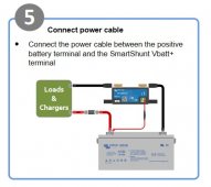
Victron 500A Shunt: https://www.altestore.com/store/met...attery-shunts-p41526/?afmc=29#VICSMRTSHUNT500
Products of what I'm planning on using are above (in the case there is something that I missed, like volts or amps or watts for something).
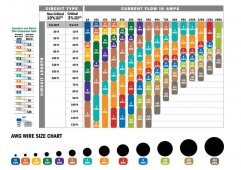
I'm planning on using 4AWG (is that's the right term? 4 Gauge wire) on most every major wiring - hooking the Batteries together will be 2AWG wire, and Solar panels and shunt, and appliances, will be their own respective gauge wire.
I went with a 40 amp SCC because I read that they can handle a higher input, they just don't output anything higher than 40 amps (Clarification on this issue would be appreciated. Also I'm not opposed to having 2 40 amp SCC's I just need clarification/direction on how to wire them together/into the system together.)
I'm also looking for advice on whether I need more fuses/breakers between different connections (Also links/direction to where I can find said products). I read that it's good to have a shut off between the Solar Panels and the SCC, but didn't find what to use for that.
Like probably many people here, I'm a complete newbie at this, so apologies for any questions that may seem idiotic to answer and if I asked too many. But I'll appreciate any help what-so-ever, so that I do this correctly the first time, and not lose 'life, limb, or eyesight' in the future.
Thanks,
Andrew


