diy solar

diy solar

Van solar system - does this make sense?

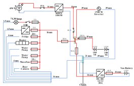
Comments on your diagram.


Fuse in solar panel feed not required. An isolation switch in place of the fuse would be useful.

All fuses as near as practical to the power source , the batteries, not as shown.

You need positive and negative buss bars near the battery.

with a 450 watt panel a Victron 100/30 will be OK.

You need more system fuses, a 50A between the battery and the cable to the DC to DC converter.
With the DC to DC both the positive and negative cables need to be 16mm2.

the inverter cables 35mm2 if short run , if over 2 meter 50mm2.

you need a fuse, 60A is typical, at the battery to feed the fuse box cable.

The fuses protect the cable so the connection between the positive buss bar and fuse holders should be as short as possible. A master fuse at the battery is a good idea. a bluesea MRBF could be used.

The van metal work needs to be connected to the negative and also the inverter casing.
diysolar 2.jpg


A permanent install of an inverter needs protective devices to comply with regulations in many countries if its feeding multiple circuits and appliances. Consult the inverter supplier/instructions for advice how to implement this. The risk of electric shock exists without protective circuits.


Had a think. You could reduce the fuse count by feeding the inverter from F1.
diysolar 3.jpg

Mike
 
Last edited:
You need a shunt based battery monitor- like a Victron Smartshunt or BMV712.

You need to know how full or empty your batteries are when you are living with them and depending on them. In my MotorHome my Smartshunt is my most checked item.
 
You're just amazing! Thank you so much for the feedback and the notes on this system. My ignorance is huge and every bit of information you give is of enormous value!

This is the last version of the system.
I just ordered the inverter (went for a 1500W instead as it will be enough).
Once I have it I'll go through the instructions and update this diagram very likely!
I'm also waiting for the battery monitor and the victron sensor for the batteries!
Exciting to see everything coming together. I can't wait to show you this up and running.

Some questions:
- fusing the panel is not mandatory, is there any advantage of a fuse over a breaker on this? I guess the breaker is not as precise, but it gives the option of using it as a switch also.
- mikefitz, when you say to spare a fuse, was it like I put in the diagram? Or this is not the way? I should have a wire from the battery directly to the inverter with the fuse and another one to the busbar for all the positives? Also, how to size the ground wire and bolt? As big as the biggest wire in the circuit?


Thank you once again, this is the best support I could get anywhere!
 

Attachments

  • circuit last.jpg
    circuit last.jpg
    141.3 KB · Views: 18
I'm also waiting for the battery monitor and the victron sensor for the batteries!

The Victron Smartshunt and/or BMV712 both have connections for a battery temp monitor - this is what I use. They will connect to the “VE.Smart Networking” - which will pass current and temperature to the mppt (for you low temperature cutoff).

If what you are talking about above “Victron sensor” is the Victron smart battery sense- those functions are already part of the Smartshunt/BMV712 (as long as you have the temperature sensor). You may not need that piece of equipment. Now if you want to use the Smartshunt/BMV712 to monitor your engine battery- then you would need the battery sense.

Hopefully this made sense.
 
fusing the panel is not mandatory, is there any advantage of a fuse over a breaker on this?
For a single panel no fuse is required, ( may be needed for code in domestic applications) as the panel, the power source, can never generate more current than its specified value. Having a switch is useful for maintenance on the system, you don't want solar power into the regulator if the battery is disconnected, Thus a breaker/switch may be an advantage, select a rating 1.5 to 2 times the max solar panel current.

you say to spare a fuse, was it like I put in the diagram?
Yes , with a 1500 inverter you could reduce this fuse to 200 amps, Mount this fuse as close to the battery positive as practical, keep the cable at 35mm2 to the inverter.
I should have a wire from the battery directly to the inverter with the fuse and another one to the busbar for all the positives?
This would be an option as in my first diagram.

The wire from the negative buss bar to van metal, equal or one size down from the biggest cable, 35mm2 or 25mm2. The van may have existing welded studs or captive fixing points you could use, or make your own point with a M8 or M10 bolt and nut, with a ring connector on the cable, clean any paint off the metal at the fixing point.

Your inverter case will have a 'earth' safety connection point this also connects to van metal. If a fault occurs inside the inverter on the low voltage side such that the case becomes at positive 12v, the current will flow down this wire and the feed fuse will blow. In addition a internal fault on the high voltage side would also be protected.

The idea behind all the fusing is that any fault may cause high current to flow that could overheat the cable and cause a fire. Before this happens the fuse will fail and prevent a disaster. Thus the fuses need to be positioned as close as practical to the power source, in this case the batteries. In many diagrams and display setups, such as seen on you tube, the fuses/breakers are not positioned correctly.

With the system a few suggestions.

Its useful to have battery monitoring. A Victron shunt ( either the smart shunt or the shunt from a BMV712) is connected between the battery negative and the negative buss bar. This was discussed earlier and is very useful for battery 'housekeeping'. On you long trip you will need to ensure you looking after the battery.

230 volt AC safety.

You have not indicated what appliances and circuits are connected to the inverter output. The AC , as in a house, can kill you without suitable protective systems in place. Please get professional help in this area.

There was some concern in other posts regarding shore power. If this is implemented again there are safety issues.
A simple solution for the moment is to disregard this and rely on solar and alternator charging. With modest power requirements this will be enough. If you are in need of shore power a low cost battery charger can be used, purchased in whatever country you are in.

enjoy your travels

Mike
 
Hello there!

So after muuuch time the system is finally coming to an end. We had some water infiltrations inside the van so we had to repair everything before setting the electricals.
I attach a photo of how it is for now so you can see it.
I'm super super thankful to all of you for the feedback you gave!

If you think something here is problematically mounted, I'm all ears as always.

Thank you again and have a nice day!
 

Attachments

  • IMG_20220306_185726.jpg
    IMG_20220306_185726.jpg
    229.1 KB · Views: 14
Hello again!

I noticed yesterday that when I open the breaker on the positive wire of the panel my diesel heating system (that is wired to a 12volt distribution box) turns briefly off (wich is bad because it needs to do a purging cycle before it turns off).

Any idea why would cutting the load of the panel to the MPPT make the diesel heater turn off?


Thanks a lot!
 
Put a meter on the circuit going to the heater and watch what the voltage does when you cut open the breaker between the PV and the solar charge controller.
 
Back
Top